In the realm of industrial automation, the proximity sensor stands as a silent sentinel, enabling countless processes with its non-contact detection capabilities. The journey of this critical component, from raw material to calibrated device, unfolds within a highly specialized production environment. This article provides a technical overview of a modern proximity sensor manufacturing facility, detailing the processes, controls, and engineering principles that ensure reliability and precision.
The production floor is typically segmented into distinct zones, each governed by stringent environmental and procedural protocols. The process begins in the Component Preparation and Sourcing Zone. Here, raw materials—including specialized ferrite cores, copper wire for coils, oscillation circuit components, and durable housing materials like PBT or nickel-plated brass—undergo incoming quality inspection (IQC). Advanced spectrometers and measurement systems verify material composition and dimensional tolerances against strict specifications. The coil winding process is often fully automated, with machines precisely winding thousands of turns of ultra-fine enameled copper wire onto the core, a critical step determining the sensor's electromagnetic characteristics.
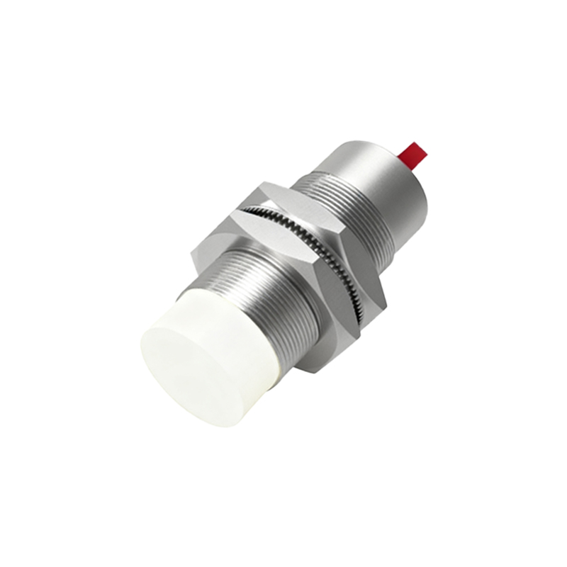
The heart of production is the Assembly and Sealing Line. This area is a showcase of precision engineering, often utilizing automated pick-and-place systems and robotic arms. The process flow is linear and controlled. The wound coil is first integrated with the oscillation circuit onto a micro PCB. This sub-assembly is then carefully placed into the sensor housing. For inductive sensors, this is followed by the potting process, where a specialized epoxy resin is injected to encapsulate the electronics. This step is crucial for environmental protection (resistance to coolants, oils, and vibrations) and long-term stability. The potting process occurs in a controlled-climate booth to prevent air bubble formation and ensure uniform curing. For capacitive or ultrasonic variants, assembly involves precise placement of electrode plates or transducer elements, with equal attention to sealing integrity.
Following assembly, units move to the Laser Marking and Cabling Station. Here, lasers etch permanent markings for part number, serial number, electrical ratings, and certification logos (e.g., CE, UL) onto the housing. Subsequently, the appropriate cable or connector is attached. For pre-wired models, this involves stripping, crimping, and soldering leads before a final potting step seals the cable entry point, guaranteeing an IP67 or IP69K rating. Strain relief mechanisms are integrated to withstand mechanical stress.
The most critical phase is the Calibration and Testing Bay. Every single sensor must pass a battery of automated functional tests. Units are placed on test fixtures that simulate real-world conditions. Key tests include:
Switch Point Accuracy Test: The sensor's detection distance is measured against a standardized target under specified voltage conditions to ensure it falls within the declared Sn (nominal sensing distance) tolerance (e.g., ±10%).
Hysteresis Verification: The difference between the switch-on and switch-off points is measured to guarantee stable switching behavior without chattering.
Frequency Response Test: For fast-cycling applications, the maximum switching frequency is verified.
Environmental Stress Screening: Samples from each batch undergo temperature cycling, vibration tests, and short-circuit tests. Electrical parameters like leakage current, voltage drop, and repeatability are logged for every unit.
Data from these tests is collected by a Manufacturing Execution System (MES), providing full traceability from component lot to finished goods.
Finally, approved sensors proceed to Final Packaging and Dispatch. They are packaged according to customer requirements, often with protective caps on the sensing face. Barcodes on the packaging link back to the production and test data. The warehouse area maintains inventory under controlled conditions before dispatch.
The entire operation is underpinned by a philosophy of Lean Manufacturing and Continuous Improvement (Kaizen). Visual management boards, 5S methodology (Sort, Set in order, Shine, Standardize, Sustain), and Statistical Process Control (SPC) charts are evident throughout the floor. Engineers constantly analyze production and test data to refine processes, reduce waste, and enhance product quality. The integration of Industry 4.0 principles, such as IoT-enabled machines feeding data to central dashboards, allows for predictive maintenance and real-time process optimization.
In conclusion, the production of a proximity sensor is far from a simple assembly job. It is a sophisticated symphony of materials science, precision mechanical engineering, electronics manufacturing, and rigorous quality assurance. The controlled, methodical environment of the production floor is what transforms theoretical designs into the robust, reliable workhorses that drive modern automated systems, ensuring each sensor performs flawlessly in the demanding conditions of the factory floor.