In industrial automation systems, proximity sensors serve as the frontline for detecting the presence or absence of objects without physical contact. A critical, yet sometimes overlooked, aspect of system reliability is the implementation of a robust "sensor trip" or "sensor broken wire" alarm program. This program is not merely a diagnostic feature; it is a fundamental safeguard against unplanned downtime, process errors, and potential safety hazards. The core principle is straightforward: the control logic must continuously monitor the sensor's signal state and trigger a specific alarm when an unexpected "open" or "off" condition is detected, indicating a sensor failure, wire breakage, disconnection, or the target moving permanently out of range.
The programming methodology varies significantly based on the sensor type—inductive, capacitive, or photoelectric—and its default wiring configuration, typically PNP (sourcing) or NPN (sinking). For a standard PNP-type, normally open (NO) proximity sensor, the expected operational logic is "high" or "1" when a target is present. The alarm condition, therefore, is a sustained "low" or "0" signal when the target should logically be present. This must be distinguished from a legitimate "no target" state. The most effective implementation uses a multi-rung logic sequence in a PLC (Programmable Logic Controller) or a structured routine in a PAC (Programmable Automation Controller).
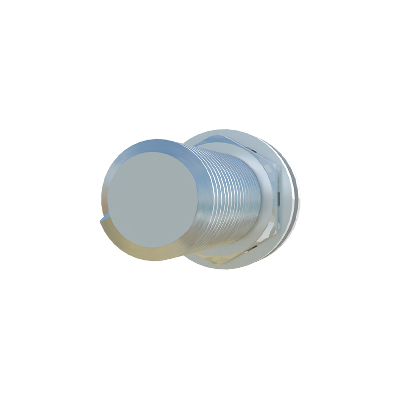
A basic yet effective alarm routine involves two primary steps: Condition Timing and Alarm Latching. First, a timer instruction is triggered by the absence of the sensor signal. For instance, if Sensor_X is critical for confirming a part in position for a machining operation, the alarm timer would start when Sensor_X is FALSE. However, to avoid nuisance alarms during normal cycle transitions, a permissive condition is essential. This permissive is often the machine cycle start signal or a related process step flag. The alarm timer only runs when the process is active and expecting the sensor to be ON. If the timer accumulates preset value—say, 2.0 seconds—this indicates an abnormal, sustained absence of signal.
Second, the timer's done bit activates an alarm latch coil. This alarm bit should be latched (sealed-in) to ensure the fault remains indicated even if the sensor signal flickers. This alarm bit then becomes part of the system's HMI (Human-Machine Interface) alarm list, triggering a visual and audible alert on the operator panel, and can be integrated into higher-level SCADA systems. For safety-critical applications, this alarm bit may also be wired to initiate a controlled machine stop or divert products to a rejection station.

For NPN sensors or normally closed (NC) configurations, the logic is inverted. An NC sensor is expected to be "high" during normal, no-target conditions. A break in the wire or sensor failure would also cause a "low" signal. Therefore, the alarm logic monitors for an unexpected "low" when the system is in a state where the sensor loop should be intact. It is crucial for engineers to thoroughly understand the sensor's datasheet and the electrical characteristics of the input card to construct the correct inverse logic.
Advanced implementations incorporate additional layers of diagnostics. This includes cross-referencing with other sensor states. For example, if a downstream sensor confirms part passage but the upstream sensor never triggered, it strengthens the diagnosis of an upstream sensor fault. Another best practice is to include a "heartbeat" or pulse test function for very critical sensors, where the controller occasionally expects a change of state within a test sequence. Furthermore, the alarm program should differentiate between types of faults where possible: a complete "wire break" (constant 0V) might be logged differently than a "shorted sensor" (constant 24V) if the input circuit can detect it, aiding maintenance technicians.
Documentation within the code is paramount. Each alarm rung should be commented with the sensor tag, location, purpose, and expected normal state. The HMI alarm message must be clear, such as "STN1: Feed Proximity Sensor Fault - Loss of Signal" rather than a generic "Alarm 47." This directs maintenance personnel swiftly to the correct location with the correct tools.
In summary, a well-designed proximity sensor trip alarm program is a hallmark of professional industrial automation design. It moves beyond basic functionality into the realm of predictive maintenance and operational intelligence. By anticipating failure modes and providing clear, actionable diagnostics, these programs significantly reduce Mean Time To Repair (MTTR), enhance overall equipment effectiveness (OEE), and fortify the safety and reliability of the entire automated process. The small investment in programming time pays substantial dividends in preventing costly production interruptions.