In the realm of industrial automation and machine safety, small proximity sensors are indispensable components. Their compact size, reliability, and non-contact detection capabilities make them ideal for a myriad of applications, from counting objects on a conveyor belt to ensuring precise positioning in robotic arms. However, the performance of these sensors is not guaranteed by datasheet specifications alone. Rigorous, methodical performance testing is paramount to ensure they meet the specific demands of an application in real-world operating conditions. This article outlines a comprehensive framework for testing the key performance parameters of small inductive, capacitive, and photoelectric proximity sensors.
The cornerstone of any performance test is understanding the sensor's rated operating distance (Sn). This is the nominal sensing range under ideal conditions, typically specified for a standard target. Testing begins with verifying this parameter. Using a calibrated test target (e.g., a 1mm thick square of mild steel Fe360 for inductive sensors), the target is moved slowly towards the sensor's active face along the sensor axis. The point at which the sensor's output switches is recorded as the actual switching distance. This test should be repeated multiple times to account for hysteresis—the difference between the switch-on point (approach) and switch-off point (retreat). A sensor's hysteresis is a critical feature that prevents output oscillation when a target is at the sensing edge.
Environmental factors profoundly impact sensor performance. Temperature testing is essential. Sensors should be subjected to operation within their specified temperature range, often from -25°C to +70°C for industrial models. Performance, particularly the switching distance, should be monitored at temperature extremes. It is not uncommon for the sensing range to decrease at very low temperatures and exhibit slight variations at high temperatures due to changes in internal component characteristics and housing expansion.
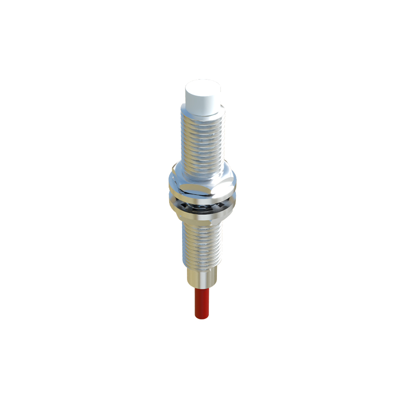
Electrical characteristics require thorough validation. This includes testing the supply voltage tolerance. A sensor rated for 10-30V DC should be tested at the lower and upper limits to ensure stable switching without false triggers or output chatter. The current consumption under load should be measured to confirm it aligns with the datasheet, ensuring compatibility with the power supply and controller input modules. For switching outputs, the voltage drop across the sensor in the "on" state (residual voltage) must be checked; an excessively high drop can lead to insufficient voltage for the connected PLC input.
Response time and switching frequency are vital for high-speed applications. To test response time, a fast-moving target (often a rotating disk with a target tab) is used. An oscilloscope is connected to monitor the sensor's output signal relative to the target's position. The delay between the target entering the sensing field and the output state change is the response time. The maximum switching frequency is derived from this, indicating how many on/off cycles the sensor can handle per second. A sensor with a 1ms response time can theoretically switch at up to 500 Hz.
Real-world interference cannot be ignored. For inductive sensors, testing for mutual interference is crucial when multiple sensors are mounted in close proximity. Adjacent sensors can dampen each other's electromagnetic fields, reducing the effective sensing range. A standard test involves mounting sensors side-by-side at a specified minimum distance and checking for any degradation in switching performance. Similarly, capacitive sensors should be tested for sensitivity to non-target materials and environmental humidity, while photoelectric sensors require testing for immunity to ambient light interference.
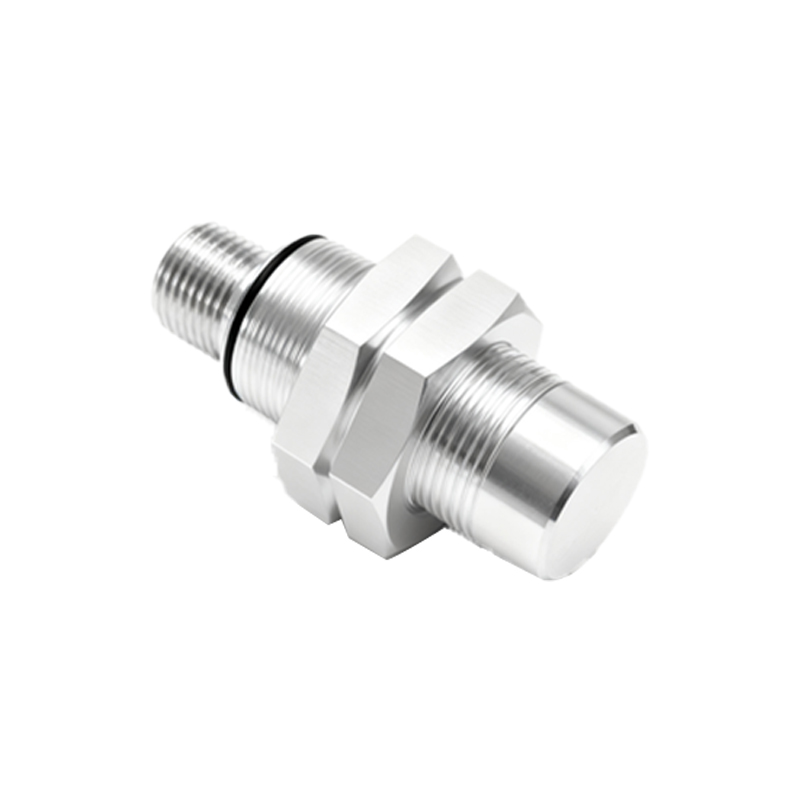
Finally, mechanical endurance and ingress protection (IP rating) testing validate robustness. This involves subjecting the sensor to vibration and shock tests per relevant standards (e.g., IEC 60068-2-6) to ensure internal connections remain secure. The IP rating, such as IP67, should be verified through dust and water immersion tests to guarantee reliability in harsh environments. Consistent performance after these stress tests is a strong indicator of long-term field reliability.
In conclusion, a systematic performance testing regimen for small proximity sensors extends far beyond a simple functional check. By methodically evaluating operating distance, hysteresis, temperature behavior, electrical parameters, dynamic response, environmental immunity, and mechanical robustness, engineers can de-risk integration, optimize machine design, and ensure unwavering reliability in automated systems. This proactive approach to validation is what separates a functional prototype from a robust, production-ready industrial application.