In industrial automation and control systems, proximity sensors are indispensable components for non-contact object detection. A correct wiring connection is paramount for ensuring sensor reliability, system safety, and optimal performance. This article, accompanied by a detailed video guide, provides a comprehensive walkthrough of standard proximity sensor wiring practices.
First, it is crucial to identify the sensor type. The two primary categories are 2-wire and 3-wire sensors. 2-wire sensors are simpler, acting as a switch in series with the load and the power supply. They are easier to install but may have a higher residual current and voltage drop. 3-wire sensors are more common and offer better performance. They have separate wires for power supply positive (brown typically), power supply negative/ground (blue), and the output signal (black). 3-wire sensors are further divided into NPN (sinking) and PNP (sourcing) output types, which determines how the output signal is switched relative to the common potential.
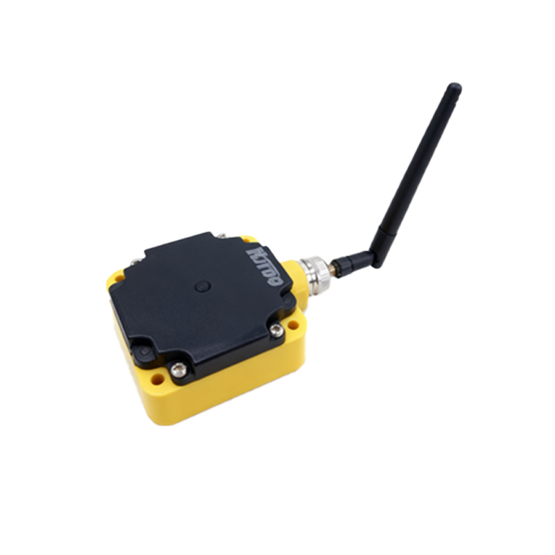
The accompanying video tutorial begins with essential safety precautions. Always disconnect power before starting any wiring work. Verify the sensor's specifications, including operating voltage (commonly 10-30V DC), output type (NPN/PNP), and current rating, against your control system's requirements.
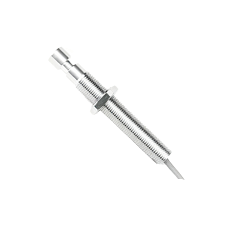
For a standard 3-wire DC sensor connection:
1. Connect the Brown wire to the positive terminal of your DC power supply (e.g., +24V).
2. Connect the Blue wire to the negative terminal or ground (0V) of the power supply.
3. Connect the Black (output) wire to your load. The load's other terminal must be connected correctly based on the output type.
For a PNP sensor: The black wire outputs positive voltage when activated. Connect the load (e.g., a PLC input, relay coil) between the black wire and the power supply negative (0V).
For an NPN sensor: The black wire sinks current to ground when activated. Connect the load between the power supply positive (+V) and the black wire.
The video clearly demonstrates both PNP and NPN wiring configurations with a programmable logic controller (PLC) digital input as the load. It highlights the importance of checking the PLC input circuit (sinking or sourcing) to ensure compatibility with the sensor's output. A mismatch will prevent the system from functioning.
For 2-wire sensor wiring, the process is more straightforward. The two wires are connected in series with the load and the power supply. Polarity is critical for DC 2-wire sensors; the manufacturer's datasheet must be consulted to identify the positive and negative leads. The video shows how to connect a 2-wire sensor to a relay coil, emphasizing the need to account for the sensor's voltage drop to ensure the relay receives sufficient voltage to operate.
The tutorial also covers critical practical aspects:
Shielded Cables: In electrically noisy environments, using shielded cables is recommended. The video shows how to properly ground the cable shield at the control panel end only to prevent ground loops and enhance noise immunity.
Short-Circuit and Overload Protection: Always install a fuse or circuit breaker in the power supply line to protect the sensor and wiring. The sensor's datasheet specifies the recommended fuse rating.
Indicator LEDs: Most sensors have an LED that indicates power and output status. The video explains how to use this LED for quick diagnostics during installation and troubleshooting.
Sensing Distance and Mounting: While not directly wiring, correct mounting (flush or non-flush) and ensuring the target object is within the specified sensing distance are vital for reliable operation. The video provides tips on alignment and testing.
Finally, the video concludes with a step-by-step commissioning checklist: power verification with a multimeter, checking the indicator LED behavior, and testing the sensor's output with the actual target material. Common pitfalls, such as incorrect NPN/PNP selection, loose connections, and ignoring environmental factors like metal proximity, are addressed.
By following the principles and visual steps outlined in this video guide, technicians and engineers can ensure robust, reliable, and safe wiring for proximity sensors in any industrial control application, minimizing downtime and maximizing system efficiency.