Proximity sensors are indispensable components in modern industrial automation, robotics, and safety systems. Their primary function is to detect the presence or absence of an object within a specified range without physical contact. However, like any precision instrument, their accuracy can drift over time due to environmental factors, mechanical wear, or component aging. Proper calibration is not merely a recommendation; it is a critical maintenance procedure to ensure system reliability, product quality, and operational safety. This guide outlines a systematic, professional approach to calibrating inductive, capacitive, and photoelectric proximity sensors.
Before initiating any calibration procedure, thorough preparation is paramount. Begin by consulting the sensor's specific datasheet and manufacturer manual. These documents contain vital information such as the sensing range, nominal operating voltage, output type (e.g., NPN/PNP, analog, IO-Link), and recommended calibration targets and conditions. Ensure the work area is clean, free from metallic debris or dust that could interfere with the process. Gather the necessary tools: a stable power supply matching the sensor's specifications, a multimeter or oscilloscope for signal verification, a set of certified gauge blocks or calibration targets made of the correct material (ferrous for inductive, various materials for capacitive), and appropriate hand tools. Always adhere to lock-out/tag-out (LOTO) procedures to de-energize the associated machinery, ensuring a zero-energy state before handling any components.
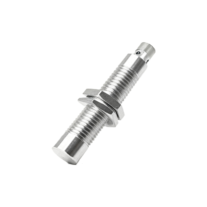
The calibration methodology varies slightly depending on the sensor technology. For a standard inductive proximity sensor with a digital (switching) output, follow these steps. First, securely mount the sensor in its operational fixture or a calibration jig. Connect it to the specified power supply and connect your multimeter to monitor the output signal. Introduce the standard target (typically a 1mm thick square of mild steel) at the exact nominal sensing distance (Sn). Adjust the sensor's potentiometer (if available) or use the teach-in function until the output state changes precisely at the target's arrival. Move the target in and out repeatedly to verify a consistent and repeatable switching point. For sensors with an analog current (4-20mA) or voltage (0-10V) output, you must calibrate at two points: the "zero" position (no target present) and the "full-scale" position (target at minimum sensing distance). Use the multimeter to measure the output and adjust the respective trim pots until the readings match the specified values, for instance, 4.00mA and 20.00mA.
Capacitive sensor calibration requires extra attention to the dielectric constant of the target material and environmental humidity. They are often calibrated in-situ for level detection. After installation, with the tank or vessel empty, adjust the "null" potentiometer until the output is at its minimum state. Then, fill the vessel with the actual process material to the desired detection level and adjust the "sensitivity" or "span" potentiometer until the output switches. Photoelectric sensors, especially diffuse-reflective types, must be calibrated using the specific target of the correct color and reflectivity at the operational distance, adjusting sensitivity to avoid false triggers from background objects.
Post-calibration validation is as crucial as the calibration itself. Perform a series of tests to document the sensor's performance. Measure the actual switching distance with gauge blocks to ensure it is within the tolerance specified in the datasheet. Check the repeatability by triggering the sensor 50-100 times and recording any variance. For critical applications, perform a hysteresis test: note the switch-on point as the target approaches and the switch-off point as it recedes; the difference should be minimal and consistent. Finally, subject the sensor to simulated operational conditions, such as temperature variations or vibration, if possible, to ensure stability.
Common pitfalls during calibration include using incorrect target materials, ignoring temperature effects, and failing to account for sensor mounting (flush vs. non-flush for inductive sensors). Always document every calibration event, recording the date, technician, initial and final settings, test results, and any observations. This log forms a vital part of the equipment's predictive maintenance history. For modern smart sensors with IO-Link or digital interfaces, leverage their built-in diagnostics and parameterization capabilities, which can often store calibration data and streamline the process.
In conclusion, meticulous calibration of proximity sensors is a foundational practice for maintaining precision in automated systems. By following a disciplined, documented approach tailored to the sensor type, engineers can ensure long-term accuracy, reduce downtime from false trips, and uphold the integrity of the entire control loop. Regular calibration schedules, informed by the operating environment and criticality of the application, are a hallmark of professional industrial maintenance.