In industrial automation and electrical control systems, proximity sensors are indispensable components for non-contact object detection. A common point of observation, and sometimes concern, for maintenance technicians and engineers is the illumination of a red LED indicator on these sensors. This article delves into the technical significance, common causes, and troubleshooting steps related to a proximity sensor's red LED light, providing a clear guide for professionals in the field.
Firstly, it is crucial to understand the standard design language of sensor indicators. Typically, a solid or blinking red LED on a proximity sensor serves as a status indicator. Its primary function is to provide immediate visual feedback about the sensor's operational state. In most standard configurations, a steadily illuminated red LED signifies that the sensor is powered correctly and is in its normal "detection" state. This means the sensor's internal oscillator circuit is active, and it is emitting its electromagnetic or ultrasonic field. When a target object enters the sensing range, the sensor's output state changes (e.g., from OFF to ON, or PNP to NPN switching), but the red LED often remains steadily lit to indicate power and readiness. Some sensor models may cause the LED to brighten, dim, or blink upon detection, but this is model-specific.
However, a red LED can also indicate issues. The context of its illumination is key. If the sensor is powered but no target is within its specified range, a steady red light is usually normal. Problems arise when the expected behavior deviates. For instance, if the sensor fails to trigger its output relay or solid-state switch despite the red LED being on and a target present, this points to a potential output circuit failure or load issue. Conversely, if the red LED is off when power is applied, it suggests a power supply problem, a wiring fault (reverse polarity, broken wire), or a complete sensor failure.
One frequent scenario causing confusion is sensor overload or short-circuit conditions. Many modern inductive or capacitive proximity sensors incorporate short-circuit and overload protection. When such a fault is detected in the output circuit, the sensor may enter a protective mode. In this state, the red LED might blink in a specific pattern (e.g., two short blinks followed by a pause) to indicate a fault code. Consulting the sensor's datasheet or manual is essential to decode these blink patterns, as they are manufacturer-specific.
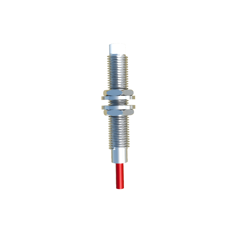
Environmental factors are another major consideration. Excessive accumulation of metallic dust on an inductive sensor's face can cause the red LED to remain constantly on, as the dust is perceived as a permanent target—a condition known as "masking." Similarly, for capacitive sensors, changes in ambient humidity or the presence of contaminating fluids can alter the dielectric constant, leading to false triggering and a constantly lit LED. Ensuring the sensor has the correct IP rating for its environment and performing regular cleaning are critical preventive measures.
Electrical interference (EMI) from nearby high-frequency drives, welding equipment, or power lines can also destabilize a sensor. This interference might cause the red LED to flicker erratically or stay on when it shouldn't. Proper practices such as using shielded cables, grounding the shield at the controller end, maintaining distance from noise sources, and installing ferrite cores can mitigate these issues.
During installation and wiring, a simple mistake like confusing the sensor's Brown (typically +V), Blue (typically 0V or common), and Black (output) wires according to the DC PNP or NPN scheme can lead to unexpected LED behavior. Always verify the wiring diagram. Furthermore, using a power supply voltage outside the sensor's specified range (e.g., applying 24V DC to a 10-30V DC sensor is fine, but applying 110V AC is catastrophic) will likely damage the unit, possibly resulting in a permanently off or permanently on LED.
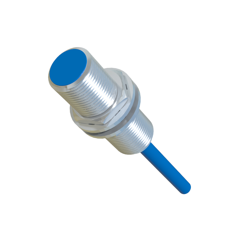
Troubleshooting should follow a logical sequence. Start by verifying the power supply voltage at the sensor's terminals with a multimeter. Check the wiring connections for tightness and corrosion. Consult the manufacturer's manual to confirm the exact meaning of the LED status for that specific model number. If possible, test the sensor in a clean, controlled environment with a standard target. Monitor the output signal with a multimeter or PLC input indicator to see if it correlates with the LED state and target presence.
In summary, the red LED on a proximity sensor is a powerful diagnostic tool. A steady red light is most often a sign of normal operation and power availability, not an alarm. Engineers must move beyond the instinct to associate "red" with "fault" and instead interpret the indicator within the full system context: sensor model specifications, wiring, environmental conditions, and output device response. By systematically analyzing these factors, electrical professionals can quickly distinguish between normal operation and genuine faults, ensuring minimal downtime and optimal performance of automated systems. Always prioritize consulting the specific product