Laser displacement sensors are critical components in modern manufacturing, quality control, and automation systems. They provide non-contact, high-precision measurements of distance, thickness, or position. However, to ensure reliable and accurate data, proper calibration and debugging are essential. This guide outlines practical steps and best practices for setting up and troubleshooting these sensors.
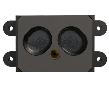
The first step in debugging a laser displacement sensor is understanding its basic operating principle. Most models work by emitting a laser beam onto a target surface. The reflected light is captured by a receiver, and the sensor calculates the distance based on the position of the reflected spot or the time-of-flight. Before installation, consult the manufacturer's datasheet for specifications like measurement range, resolution, linearity, and environmental limits (temperature, humidity, ambient light).

Begin with mechanical and electrical installation. Mount the sensor securely using a stable bracket to minimize vibration, which can cause measurement noise. Ensure the sensor is perpendicular to the target surface unless specified otherwise. For angled measurements, account for cosine error. Electrical connections must follow the wiring diagram: typically, power supply (often 12-24V DC), output signals (analog voltage/current or digital interfaces like RS-485/Ethernet), and possibly trigger inputs. Use shielded cables and proper grounding to reduce electromagnetic interference.
Power on the sensor and access its configuration interface. Many sensors come with dedicated software or a built-in web server for setup. Connect via USB, Ethernet, or a serial port. The primary calibration steps usually involve:
1. Setting the Measurement Range: Define the start and end points within the sensor's operational limits. Some sensors allow you to teach these points by placing the target at known near and far positions.
2. Configuring Output Type: Match the output signal (e.g., 0-10V, 4-20mA) to your data acquisition system or PLC. Scale the output correctly so that the minimum measured distance corresponds to the minimum output voltage/current and vice versa.
3. Adjusting Response Time/Filters: To smooth out noise, adjust the response time or enable digital filtering (like moving average). Be cautious: excessive filtering can delay the output and mask rapid changes.
4. Setting Alarm or Trigger Thresholds: For applications needing go/no-go decisions, configure high/low limits that trigger a digital output when exceeded.

After basic configuration, perform a linearity check. Place a calibration target (e.g., a precision stage or gauge blocks) at multiple known positions across the measurement range. Record the sensor's output at each point. Compare the readings to the actual values. If significant non-linearity or offset exists, use the sensor's software to perform a multi-point linearity correction. Many advanced sensors store correction curves to compensate for systematic errors.
Environmental factors are common sources of error. Intense ambient light, especially from other lasers or sunlight, can saturate the receiver. Use the sensor in a controlled light environment or employ models with modulated laser light to reject background interference. Dust, smoke, or oil mist can scatter the beam; consider sensors with coaxial designs or protective air curtains. Temperature fluctuations affect both the sensor electronics and the target material's thermal expansion. For high-precision tasks, choose sensors with temperature compensation or stabilize the operating environment.
Troubleshooting typical issues involves methodical checks:
* No Output or Erratic Readings: Verify power supply voltage and polarity. Check cable connections for looseness or damage. Ensure the target surface is within the specified range and that its optical properties (color, reflectivity, texture) are suitable. Very dark, transparent, or glossy surfaces may require special sensors or surface treatment.
* Poor Repeatability: This often stems from mechanical vibration, loose mounting, or an unstable target. Reinforce mounting and isolate vibrations. Increase response time slightly to dampen noise, but verify it meets the application's speed requirements.
* Drifting Measurements: Often caused by temperature drift. Allow the sensor to warm up for the time specified in the manual (often 30 minutes) after power-on before taking critical measurements. Check for drafts or heat sources near the sensor.
* Communication Failures (for network sensors): Confirm the IP address, subnet mask, and protocol settings (e.g., Modbus TCP). Use a network tester to check cable integrity.
For integration into a larger system, synchronize the sensor with other machines. Use external trigger inputs if measuring moving objects on a conveyor to capture data at precise moments. Ensure the PLC or controller program correctly interprets the scaled analog or digital values.
Regular maintenance is simple but vital. Keep the lens clean using a soft, lint-free cloth and approved cleaner. Periodically re-check calibration, especially if the operating environment changes or after physical shock. Update the sensor's firmware if the manufacturer releases patches for performance improvements.
In summary, successful debugging of a laser displacement sensor hinges on careful installation, systematic configuration tailored to the specific application, understanding environmental influences, and methodical troubleshooting. By following these steps, engineers can achieve the high levels of accuracy and stability required in demanding industrial settings.