Proximity sensors, particularly inductive ring-type sensors, are essential components in modern industrial automation. These non-contact devices detect the presence of metallic objects without physical interaction, making them ideal for high-speed counting, positioning, and safety applications. Proper wiring is critical to ensure reliable operation, longevity, and system safety. This guide provides a comprehensive overview of wiring practices for ring-type proximity sensors, adhering to industry standards and best practices.
First, understand the basic components. A typical ring-type proximity sensor consists of a sensing coil embedded within a ferrite core ring, an oscillator, a trigger circuit, and an output switching device. The sensor generates an electromagnetic field; when a metallic target enters this field, eddy currents are induced, causing a change in oscillation amplitude. This change is detected by the trigger circuit, which activates the output. Most industrial ring sensors operate on DC voltages (commonly 10-30V DC) or AC voltages (90-250V AC), with outputs including NPN (sinking), PNP (sourcing), or relay types. Always refer to the manufacturer's datasheet for specific electrical characteristics.
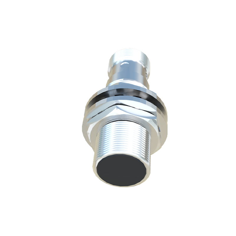
Wiring begins with power supply connections. For DC sensors, identify the positive (V+) and negative (V-) terminals. Use shielded cables to minimize electromagnetic interference (EMI), especially in environments with motors or frequency drives. Connect the V+ wire to the positive terminal of the DC power supply and the V- wire to the negative terminal. Ensure the power supply voltage matches the sensor's rated voltage. Incorrect voltage can lead to malfunction or permanent damage. For AC sensors, connect the live (L) and neutral (N) wires to the corresponding AC power terminals. Grounding is mandatory: attach a separate ground wire to the sensor's grounding terminal or the housing, connecting it to a reliable earth ground point to prevent electrical noise and enhance safety.
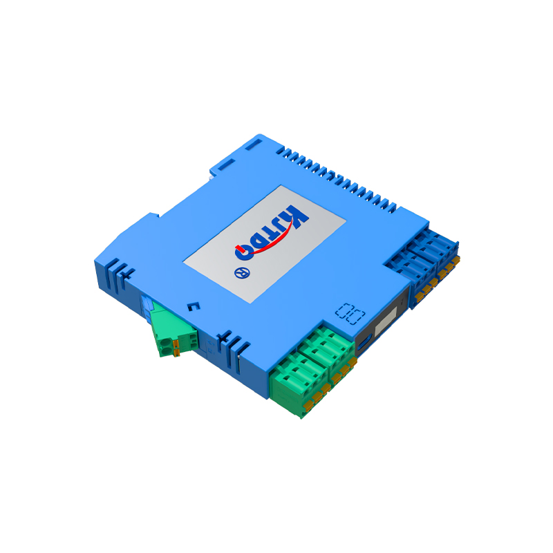
Output wiring depends on the sensor type and load. For NPN sensors (sinking output), the output terminal acts as a switch to ground. Connect one lead of the load (e.g., a PLC input, relay coil, or indicator) to the positive supply voltage. Connect the other lead of the load to the sensor's output terminal. When the sensor detects a target, the output switches to ground, completing the circuit and activating the load. For PNP sensors (sourcing output), the output terminal supplies positive voltage. Connect one lead of the load to the output terminal and the other lead to the negative supply voltage. Here, the output switches positive voltage to the load upon detection. Always verify the load current does not exceed the sensor's maximum switching capacity, typically around 200mA for standard models. Overloading can cause overheating and failure.
Ring sensors often feature auxiliary connections for diagnostics or synchronization. Some models include a diagnostic output (e.g., NO/NC contacts) to indicate sensor health or power status. Others may have synchronization wires (SYNC) for multiple sensor installations to prevent mutual interference. Connect these according to the wiring diagram, typically by linking SYNC wires between sensors or to a controller. Additionally, many sensors have LED indicators for power and detection status, which aid in troubleshooting.
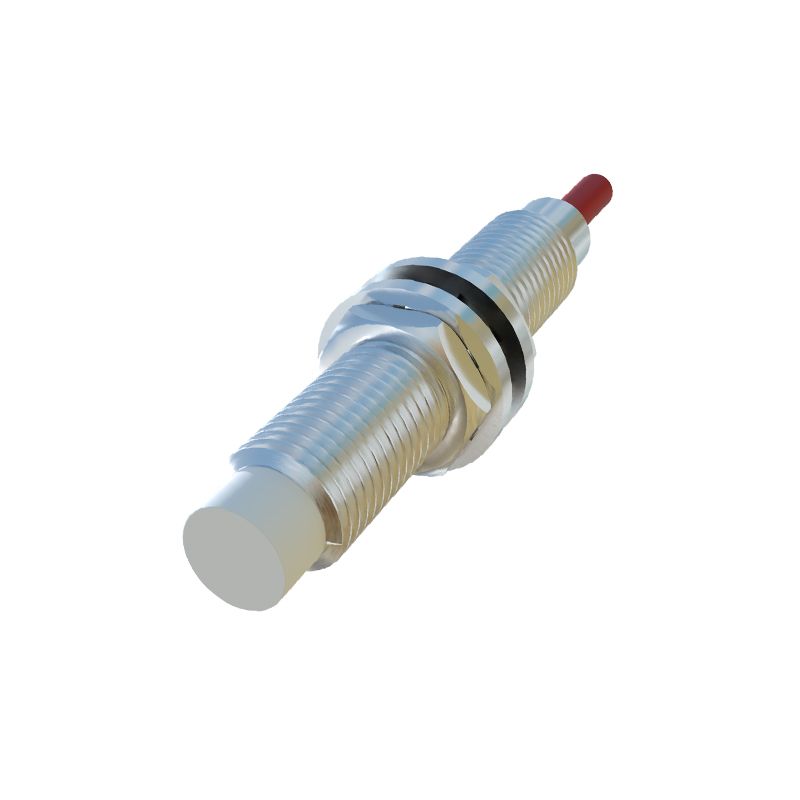
Installation practices impact performance. Mount the sensor securely, ensuring the target passes through the ring's center without physical contact. Maintain a clearance of at least one ring diameter from other metal objects to avoid false triggers. For wiring, use appropriate wire gauges (e.g., 18-22 AWG for low-current applications) and secure connections with crimp terminals to prevent loosening from vibration. Route cables away from high-voltage lines and noise sources. If using cable glands, ensure they are properly sealed for IP-rated protection in dusty or wet environments.
Testing and troubleshooting are final steps. After wiring, power on the system and observe the sensor's LED. A steady power LED indicates correct voltage supply. Introduce a target metal object; the detection LED should illuminate, and the output should switch. Use a multimeter to verify output voltage or continuity if issues arise. Common problems include no detection (check power, target material, or sensing distance), intermittent operation (inspect wiring for loose connections or EMI), or false triggers (ensure proper grounding and isolation from adjacent metal). Always de-energize the circuit before making any wiring changes.
In summary, wiring a ring-type proximity sensor involves careful attention to power requirements, output configuration, and environmental factors. By following these guidelines, engineers can ensure optimal sensor performance, contributing to efficient and safe industrial automation systems. Regular maintenance and adherence to standards like IEC 60947-5-2 further enhance reliability.