Embedded proximity sensors are critical components in modern industrial automation, offering non-contact detection of metallic and non-metallic objects. Proper installation is paramount to ensure optimal performance, longevity, and system reliability. This guide details the essential procedures and considerations for installing embedded proximity sensors, adhering to industry best practices.
Pre-Installation Planning and Site Assessment
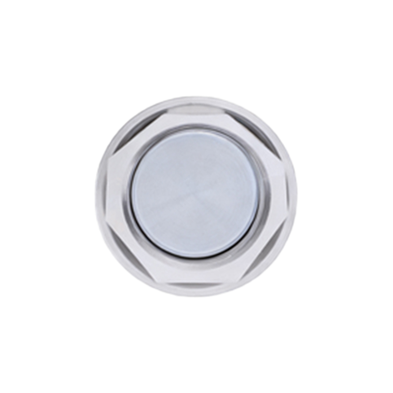
Before physical installation begins, a thorough site assessment is mandatory. First, verify the sensor's specifications—sensing distance, supply voltage, output type (PNP/NPN, NO/NC), and housing material—against the application requirements. Consider the target object's material, size, shape, and approach direction. The effective sensing distance (Sn) can be reduced when embedded in metal, a factor accounted for in the sensor's datasheet. Ensure the mounting location is accessible for wiring and future maintenance. The environment must be evaluated for potential contaminants like cutting fluids, metal chips, dust, or strong electromagnetic fields, which may necessitate sensors with higher IP (Ingress Protection) ratings or specialized shielding.
Mounting Procedure and Mechanical Integration
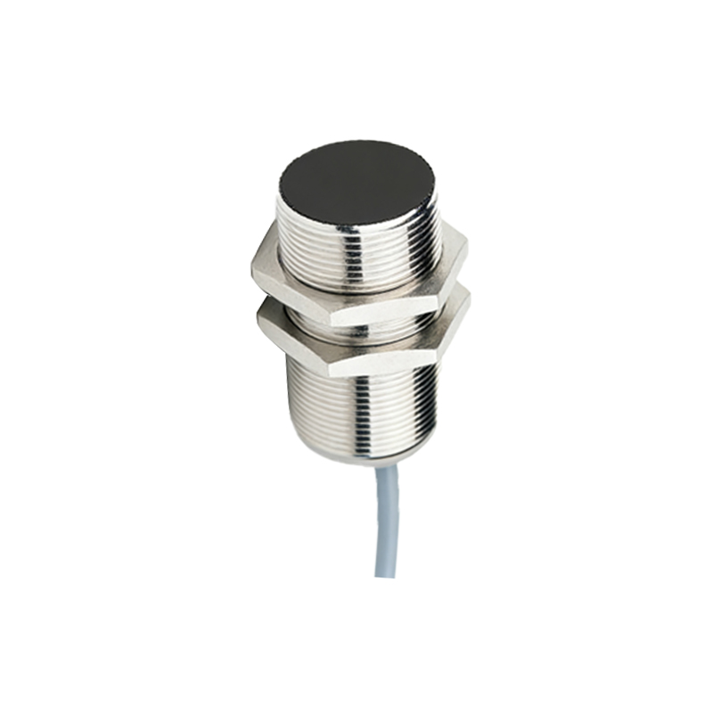
The core principle of embedding is to flush-mount the sensor into a metal bracket or machine structure. The mounting hole must be machined to the precise diameter and depth specified by the manufacturer, typically with a tolerance of H7 or as recommended. A loose fit can cause positional drift, while an overtight fit may damage the housing. The sensing face must be perfectly flush with the mounting surface; any protrusion risks physical damage, and any recess reduces the effective sensing range. For cylindrical sensors, use the supplied lock nut or a suitable mounting bracket to secure the sensor. Avoid overtightening, as this can distort the housing and affect performance. It is crucial to maintain the recommended clearance around the sensing face—a concentric or lateral non-metallic zone free of surrounding metal to prevent false triggering or shielding effects. Always refer to the installation diagrams in the technical manual.
Electrical Wiring and Connection Standards
Electrical installation demands strict adherence to safety protocols. Disconnect all power sources before proceeding. Use shielded, multi-conductor cables suitable for industrial environments. For DC sensors, correctly identify the brown wire (typically +V), blue wire (0V/Common), and black wire (load/output). Connect the shield to ground at the control cabinet end only, avoiding ground loops. Ensure wires are securely fastened using cable glands or strain relief connectors to prevent pull-out from vibration. Route signal cables away from high-voltage power lines and motor drives to minimize electromagnetic interference (EMI). If using multiple sensors in close proximity, maintain adequate spacing between them to prevent mutual interference. For AC sensors or special models, follow the specific wiring schematic provided. After connections are made, perform a continuity and insulation resistance check.
Alignment, Testing, and Commissioning
Once mechanically and electrically installed, precise alignment with the target object is critical. The target should approach the sensor's sensing face perpendicularly for maximum reliability. Use alignment tools or jigs if necessary. For standard applications, the target object should be at least 1.5 times the sensor's stated sensing distance away during the alignment check. Power on the system and conduct functional tests. Use the sensor's indicator LED (if equipped) and a multimeter or PLC input monitor to verify switching behavior. Test with the target at the maximum required sensing distance and under worst-case conditions (e.g., covered in oil, at temperature extremes). Adjust the sensor's position minutely if the switching point is inconsistent. Document the final installation parameters, including mounting torque, clearance, and tested sensing distance, for future reference.
Maintenance and Troubleshooting Tips
Regular maintenance ensures sustained performance. Periodically inspect the sensor's face for buildup of contaminants and clean it with a soft, lint-free cloth and appropriate solvent. Check the mechanical integrity of the mount and cable connections. Common issues include failure to detect, constant ON/OFF state, or shortened sensing range. Troubleshooting steps involve verifying power supply voltage, checking for target material compatibility, inspecting for physical damage or misalignment, and testing for electrical noise interference. Always compare performance against the baseline established during commissioning.
In conclusion, the correct installation of embedded proximity sensors is a systematic process combining meticulous planning, precise mechanical execution, careful electrical work, and rigorous testing. Neglecting any single aspect can lead to premature failure, unreliable machine cycles, and costly downtime. By following these engineered guidelines, technicians and engineers can ensure these sensors deliver their full potential in creating robust and efficient automated systems.