Proximity sensors are essential components in industrial automation, providing non-contact detection of objects. Proper wiring is critical to ensure reliable operation and safety. This guide illustrates common wiring methods for both 2-wire and 3-wire DC proximity sensors, along with AC types, using clear diagrams and step-by-step explanations.
For 2-wire DC sensors, wiring is straightforward but requires attention to load compatibility. The sensor is connected in series with the load and power supply. Brown wire (typically positive) connects to the positive voltage supply, while the blue wire connects to the load. The load's other terminal then connects to the power supply negative. A key consideration is the voltage drop across the sensor; ensure the residual voltage at the load meets its minimum requirement. Always verify the sensor's leakage current when off, as high leakage might keep some loads activated.
3-wire DC sensors offer separate power and switching circuits, improving performance. They come in NPN (sinking) and PNP (sourcing) configurations. For a 3-wire NPN sensor: connect the brown wire to positive DC, blue to negative DC (common), and the black wire (output) to the load. The load's other side connects to positive. When the sensor activates, it sinks current to negative, switching the load. For a PNP sensor: brown to positive, blue to negative, and black output to the load. The load's other side connects to negative. Here, the sensor sources current from positive to the load. Always match the sensor type (NPN/PNP) with your PLC or controller input specifications. Incorrect matching can cause malfunction.
AC proximity sensors usually have two or three wires. For a 2-wire AC sensor, connect one wire (often brown) to the AC line (hot) and the other (blue) to the load. The load connects to the AC neutral. These sensors have higher leakage current; use a load with adequate minimum current to ensure proper turn-off. For 3-wire AC sensors, additional shielding or ground wires (green/yellow) are present for safety grounding, reducing electrical noise.
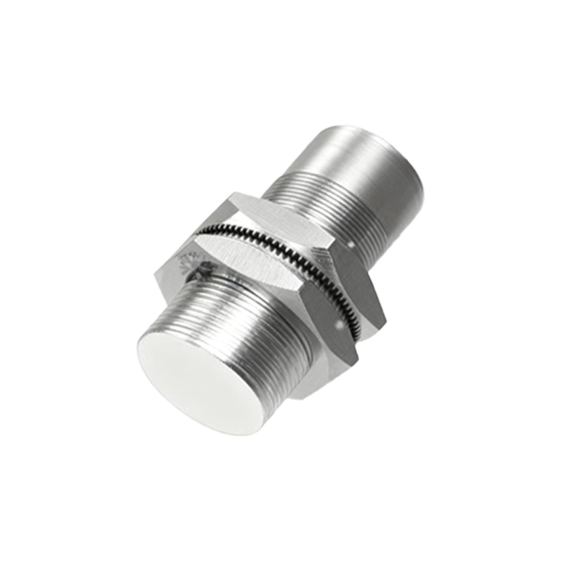
Shielded cables are recommended for long runs or electrically noisy environments. Connect the shield to ground at one end only, typically at the controller side, to prevent ground loops. Always follow the manufacturer's datasheet for voltage ratings, wire sizes, and temperature limits. Use appropriate conduit and strain relief to protect wires from physical damage.
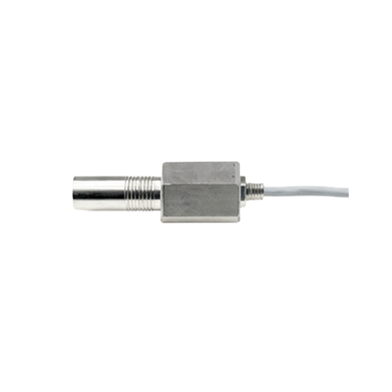
For wiring to a PLC digital input, identify whether the input is sinking or sourcing. A sinking input (common on many PLCs) requires a PNP sensor. Connect the sensor output to the PLC input, and the PLC common to negative. A sourcing input requires an NPN sensor. Double-check the PLC manual to avoid damage.
When connecting multiple sensors, avoid daisy-chaining power wires directly from one sensor to another. Instead, use a dedicated power distribution block to ensure stable voltage for each sensor. This prevents voltage drops that could cause inconsistent operation. For sensors with diagnostic outputs (like NO/NC contacts), wire them according to the required fail-safe logic.
Testing is crucial after wiring. Use a multimeter to check voltage at the load with the sensor active and inactive. Verify switching response time meets application needs. For inductive sensors, ensure the target material (e.g., steel, aluminum) is within the specified sensing range, as different materials affect performance.
In summary, correct proximity sensor wiring hinges on understanding sensor type, load requirements, and environmental factors. Always de-energize circuits before wiring, and adhere to local electrical codes and safety standards. Proper installation maximizes sensor lifespan and system reliability.