In the realm of industrial automation and electrical engineering, proximity sensors are indispensable components for non-contact detection. Their reliability and precision are paramount, and the manufacturing process, particularly injection molding, plays a critical role in determining their final performance, durability, and cost-effectiveness. This article delves into the intricacies of proximity sensor injection molding, providing a detailed technical overview for industry professionals.
The housing of a proximity sensor is its first line of defense against harsh industrial environments. It must withstand factors like moisture, dust, chemicals, mechanical impact, and electromagnetic interference. Injection molding is the predominant manufacturing method for these plastic or polymer housings due to its ability to produce complex, high-precision, and repeatable parts at scale. The process begins with material selection. Engineering thermoplastics such as Polyamide (PA, Nylon), Polybutylene Terephthalate (PBT), and Polycarbonate (PC) are commonly chosen. These materials offer an excellent balance of mechanical strength, dimensional stability, temperature resistance, and, crucially, dielectric properties. For sensors operating in washdown or corrosive environments, materials like Polyphenylene Sulfide (PPS) or specific grades of Polypropylene (PP) may be specified. The selection directly impacts the sensor's IP (Ingress Protection) rating, a key specification for engineers.
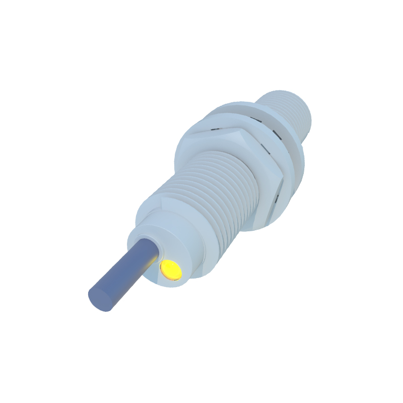
The mold design phase is where engineering precision meets manufacturability. A high-quality mold, typically made from hardened steel, is a significant investment but is essential for part consistency. Critical design considerations include gate location, which affects material flow and can influence sensor performance by inducing stress; wall thickness uniformity to prevent sink marks and warpage; and the incorporation of intricate features for cable glands, mounting threads, and LED indicator windows. Venting is crucial to avoid air traps that can cause burns or incomplete filling. For inductive proximity sensors, which detect metallic objects, the mold must also precisely form the "sensing face" area. This region is often molded from a specific material, like PTFE-filled polymer, that allows the electromagnetic field to pass through with minimal attenuation. The co-injection or two-shot molding process is sometimes employed here to combine a robust housing material with a specialized sensing face material in a single operation.
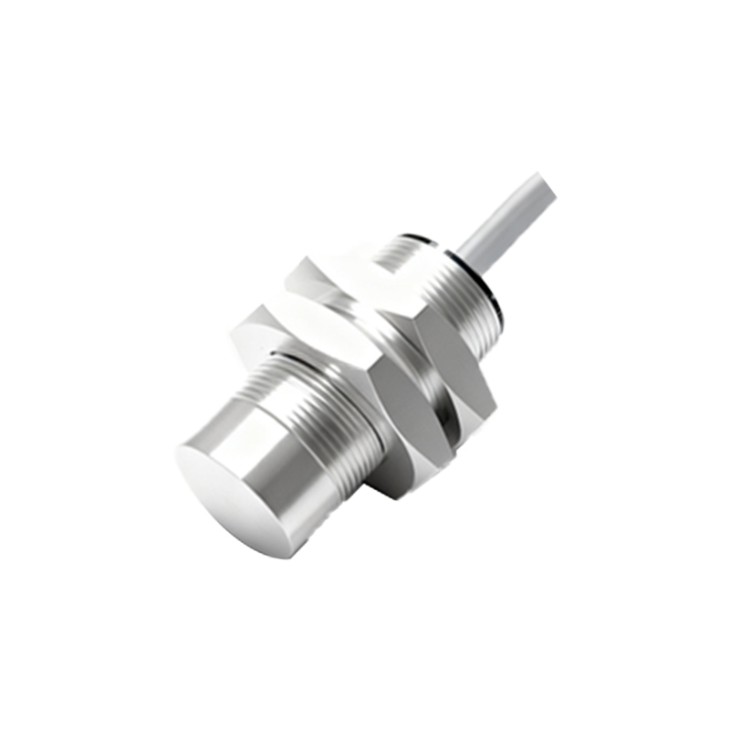
The injection molding process itself requires stringent control. Parameters such as melt temperature, injection speed and pressure, packing pressure, and cooling time must be optimized for the specific material and part geometry. Inconsistent melt temperature can lead to variations in material viscosity, affecting fill patterns and part dimensions. Excessive injection speed might cause jetting or molecular orientation that weakens the part. Insufficient packing pressure can result in shrinkage and voids, compromising the housing's seal integrity. The cooling phase must be controlled to ensure the part solidifies uniformly, minimizing internal stresses that could lead to long-term deformation or cracking. Post-molding, parts often undergo secondary operations like deflashing (removing excess material from parting lines), ultrasonic welding to seal the housing, and laser marking for part numbers and logos.
Quality assurance is integrated throughout the production cycle. First-article inspection using Coordinate Measuring Machines (CMM) verifies critical dimensions against the CAD model. Process monitoring systems track key parameters in real-time, flagging any deviations from the established process window. Finished sensor housings undergo functional tests, including IP rating tests (e.g., IP67 or IP69K) to verify sealing against dust and water ingress. For the sensing element, which is typically a wound coil and ferrite core potted inside the housing, the molding process must ensure perfect encapsulation. This potting process, often using epoxy resins, protects the electronics from vibration, thermal cycling, and moisture. Any voids or delamination in this potting compound can lead to premature sensor failure.
In conclusion, proximity sensor injection molding is far more than a simple shaping process. It is a sophisticated discipline that sits at the intersection of materials science, mechanical design, process engineering, and electrical functionality. For electrical engineers specifying or integrating these sensors, a fundamental understanding of this manufacturing process enables more informed material selections, more robust design reviews, and better troubleshooting of field failures. As sensor technology advances towards miniaturization and enhanced intelligence, the demands on injection molding will only grow, requiring continued innovation in materials, mold design, and process control to meet the ever-increasing standards of industrial automation.