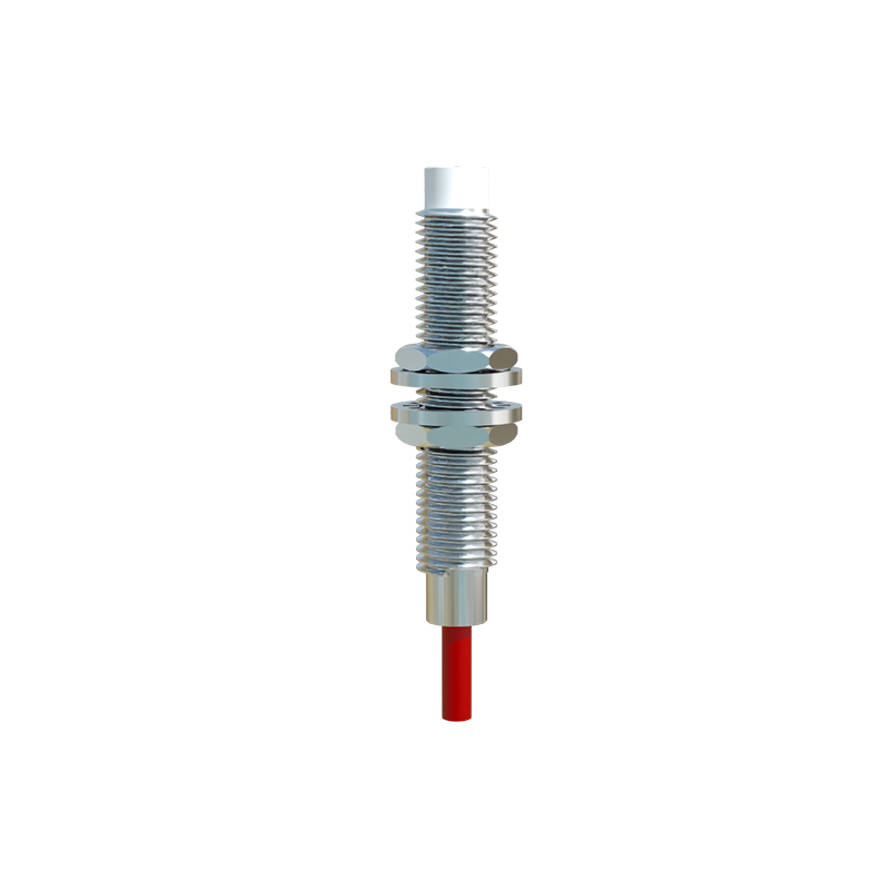
In industrial automation and control systems, proximity sensors are indispensable components for non-contact detection of metallic or non-metallic objects. Their reliability is paramount for ensuring seamless operations, safety, and efficiency. However, engineers frequently encounter scenarios where these sensors become unresponsive, erratic, or fail entirely. Understanding the root causes and implementing systematic solutions is a critical skill. This article delves into the common reasons for proximity sensor malfunctions and provides a structured troubleshooting guide from an electrical engineering perspective.
A primary culprit behind sensor failure is environmental contamination. Industrial settings often expose sensors to oil, coolant, metal chips, dust, and conductive debris. For inductive sensors, a buildup of metallic particles on the sensing face can create a false shield, effectively reducing the nominal sensing distance or causing permanent activation. Similarly, capacitive sensors can be triggered erroneously by dust or moisture adhering to the surface. Regular cleaning with appropriate solvents and implementing physical barriers or air blow-offs are essential preventive measures. Ensuring the sensor's IP (Ingress Protection) rating matches the environmental severity is a fundamental design consideration often overlooked during installation.
Electrical interference and improper wiring constitute another major failure domain. Inductive and capacitive sensors are susceptible to electromagnetic interference (EMI) from nearby motors, variable frequency drives (VFDs), welding equipment, or high-current cables. This can manifest as sporadic triggering or signal noise. Solutions include using shielded cables, grounding the shield properly at the controller end only, maintaining physical separation from noise sources, and employing sensors with built-in noise immunity. Wiring errors, such as incorrect polarity for DC sensors, overloaded outputs, or voltage spikes, can cause immediate or gradual damage. Always verify the datasheet specifications for voltage range, current sink/source capability, and wire gauge. Incorporating surge suppressors or flyback diodes for inductive loads connected to the sensor output can prevent back-EMF damage.
Sensor selection and mechanical misalignment are frequently underestimated factors. Using an inductive sensor to detect a non-ferrous metal like aluminum or copper at its standard range will result in a significantly reduced effective sensing distance, often perceived as a failure. Selecting a sensor specifically designed for non-ferrous metals (with a factor-1 correction) is crucial. Ultrasonic and capacitive sensors are alternatives for non-metallic targets. Mechanical issues, such as misalignment between the sensor and the target, vibration causing movement outside the sensing field, or an incorrect gap exceeding the sensor's specified range, will lead to unreliable operation. Implementing precise mounting fixtures and regularly checking alignment during maintenance cycles are vital. The target object's size and material must also meet the minimum requirements specified by the sensor's manufacturer.
Internal component degradation over time is inevitable. Proximity sensors contain oscillators, amplifiers, and output circuits that can degrade due to thermal stress, voltage transients, or simply prolonged use. The oscillator coil in inductive sensors can weaken, reducing sensitivity. Output transistors can fail in a shorted or open state. While individual component repair is rarely cost-effective, monitoring performance trends can predict end-of-life. A gradual reduction in sensing distance or an increase in response time often signals impending failure, allowing for planned replacement.
A systematic diagnostic approach is key. Start with a visual and environmental inspection for contamination, physical damage, and correct installation. Next, use a multimeter to check the supply voltage at the sensor terminals under load to rule out voltage drop issues. Monitor the output signal with a multimeter or oscilloscope to see if it switches cleanly between states (e.g., 0V and 24V for a PNP sensor) when a target is presented. A logic probe or PLC input indicator can also confirm signal presence. If the sensor seems operational but the system isn't responding, trace the circuit back to the controller, checking for broken wires, faulty connectors, or a malfunctioning input module. Swapping the sensor with a known-good unit from a similar application is a quick and effective isolation test.
Ultimately, preventing proximity sensor failures hinges on a triad of correct selection, proper installation, and proactive maintenance. Adhering to manufacturer specifications for environment, load, and electrical characteristics cannot be overstated. By methodically addressing environmental, electrical, mechanical, and wear-related factors, electrical engineers can ensure the high reliability of these critical sensing elements, minimizing downtime and maintaining robust control system integrity.