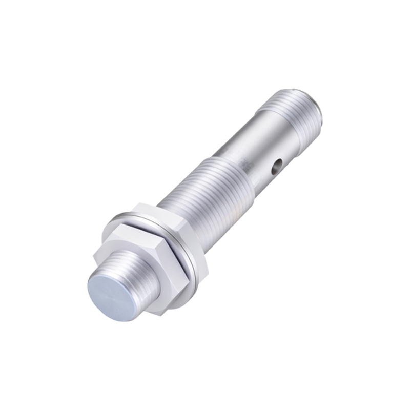
In industrial automation and control systems, proximity switch sensors are indispensable components for non-contact detection of metallic or, in some cases, non-metallic objects. Their reliability directly impacts the efficiency and safety of machinery. However, these sensors, particularly inductive and capacitive types, are often installed in harsh electrical environments characterized by voltage transients, electromagnetic interference (EMI), reverse polarity, and short-circuit risks. Without proper protection, sensor failure is not a matter of "if" but "when," leading to costly downtime. This article delves into the design and implementation of robust protection circuits for proximity sensors, focusing on practical, industry-proven solutions.
The primary threats to a proximity sensor's longevity originate from its power supply lines and signal output lines. On the power side, voltage spikes from inductive load switching (e.g., solenoids, contactors, motors on the same circuit) are a major culprit. These spikes can far exceed the sensor's nominal voltage rating. On the signal output side, for sensors with solid-state outputs (PNP/NPN), risks include overcurrent from a short to ground or supply, and back-EMF from inductive loads like relay coils connected to the output.
A comprehensive protection strategy employs a multi-layered approach, often called "defense in depth."
1. Power Line Protection:
Reverse Polarity Protection: The simplest yet most crucial element. A series diode (Schottky for lower voltage drop) in the positive supply line prevents damage if wires are accidentally connected backwards. For DC sensors, this is a minimum requirement.
Transient Voltage Suppression (TVS): A TVS diode, or a bidirectional one for AC sensors, is placed in parallel (shunt) across the power input terminals. It clamps any voltage spike above its breakdown voltage to a safe level, diverting the surge current away from the sensor's internal circuitry. Selection criteria include standoff voltage (slightly above operating voltage), peak pulse current rating, and clamping voltage.
LC Filters: A small ferrite bead or inductor (L) in series with the supply line, combined with a bulk and decoupling capacitor (C) to ground, forms a low-pass filter. This suppresses high-frequency noise and EMI, which can cause erratic switching behavior.

2. Output Line Protection:
For Switching Inductive Loads: When a sensor's output drives a relay, solenoid, or small contactor coil, the sudden interruption of current when the output turns off generates a high-voltage back-EMF spike (L di/dt). This can destroy the sensor's output transistor.
Freewheeling Diode: The standard solution. A diode is placed in reverse bias across the inductive load. When the output turns off, the induced current circulates ("freewheels") through the diode, safely dissipating the energy. The diode's reverse voltage rating must exceed the supply voltage.
Metal-Oxide Varistor (MOV) or TVS Diode: For faster clamping, a MOV or TVS diode across the load offers robust protection, though a diode is typically more effective for DC coils.
RC Snubber Network: A resistor and capacitor in series across the load or the sensor's output terminals can dampen voltage transients, useful for AC loads or where diode-induced release delay is unacceptable.
Overcurrent/Short-Circuit Protection: A small, fast-acting fuse or a resettable Polymeric Positive Temperature Coefficient (PPTC) device in series with the output can protect against sustained overcurrent or a direct short. For integrated solutions, some sensor models feature built-in electronic short-circuit protection.
3. Integrated Solutions and Layout Considerations:
Many modern proximity sensors incorporate basic protection like reverse polarity and short-circuit protection internally. However, for extreme environments, external supplementary protection is still recommended. Physical layout is equally critical: keep sensor cables away from high-power cabling, use shielded cables with the shield properly grounded at the control panel end, and minimize cable length to reduce antenna effects.
Implementation Example:
Consider a 24VDC, 3-wire PNP (sourcing) inductive proximity switch controlling a 24V relay coil. A recommended protection circuit would include:
Power Input (Brown wire): Series Schottky diode (e.g., 1N5819) + Bidirectional TVS diode (e.g., P6KE24CA) to ground + 100nF ceramic capacitor to ground.
Output (Black wire): Freewheeling diode (e.g., 1N4007) across the relay coil terminals. A PPTC (e.g., 100mA hold current) in series with the output provides resettable short-circuit