Proximity sensors are indispensable components in modern industrial automation, robotics, and safety systems. Understanding their structural composition is crucial for engineers and technicians involved in design, installation, and maintenance. This article provides a detailed breakdown of a standard inductive proximity sensor's structural diagram, explaining the function of each component in line with industry terminology and practices.
A typical inductive proximity sensor, designed to detect metallic objects without physical contact, consists of several key internal assemblies housed within a robust casing. The primary structural elements can be categorized into the sensing head, the oscillator and detection circuit, the output stage, and the housing.
1. Sensing Head and Core Assembly:
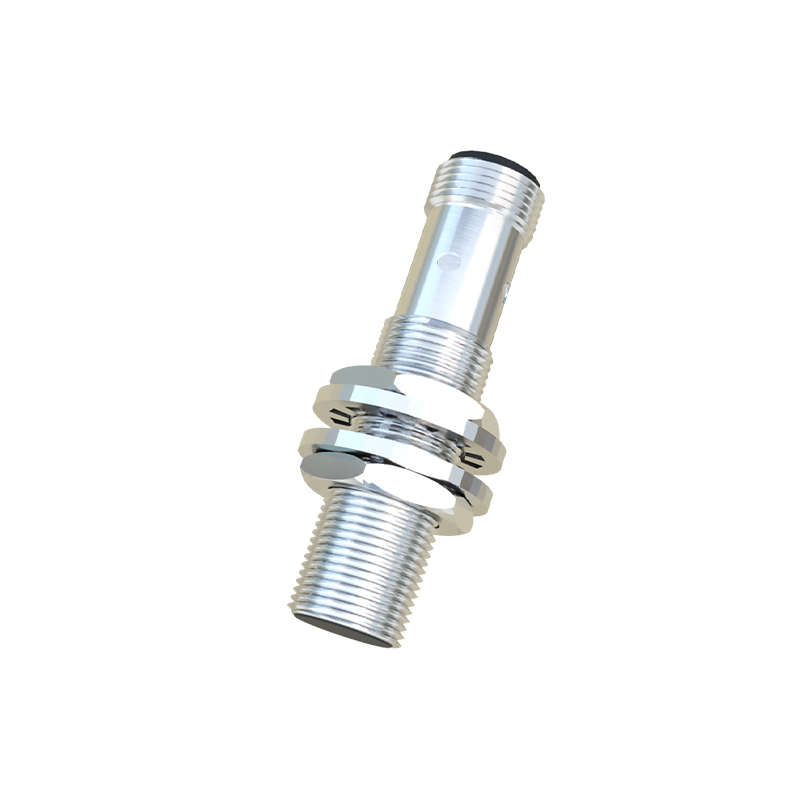
At the forefront is the sensing face, usually made of a wear-resistant polymer or ceramic material. Directly behind it lies the core component: a ferrite core wound with a coil. This coil is part of an LC resonant oscillator circuit. The sensing face is engineered to allow the high-frequency electromagnetic field generated by the oscillator to emanate towards the target area while protecting the internal coil from physical damage and environmental contaminants.
2. Oscillator, Demodulator, and Signal Processing Circuitry:
The heart of the sensor is the oscillator circuit, which generates a high-frequency alternating magnetic field at the sensing face. When a metallic target enters this field, eddy currents are induced on the target's surface. This causes a change in the oscillation amplitude or frequency within the sensor's coil. This minute change is detected by a subsequent demodulator circuit, which converts the AC signal into a DC voltage level. This DC signal is then fed into a threshold detector or Schmitt trigger circuit. The trigger circuit is critical for providing a clean, stable switching signal, eliminating chatter and ensuring reliable operation despite minor fluctuations in the sensed signal.
3. Output Stage and Wiring:
The processed signal activates the output stage. For a solid-state DC sensor, this typically involves a transistor (NPN or PNP) that switches the load connected to the output wire. The output is often configured as a 3-wire design: brown wire for DC supply positive (+V), blue wire for common negative (0V), and black wire for the switched output signal. Some models include additional wires for diagnostic functions or complementary outputs. Protection components, such as reverse polarity protection diodes, overvoltage protection, and short-circuit protection, are integrated into this stage to enhance durability.
4. Housing and Connector Assembly:
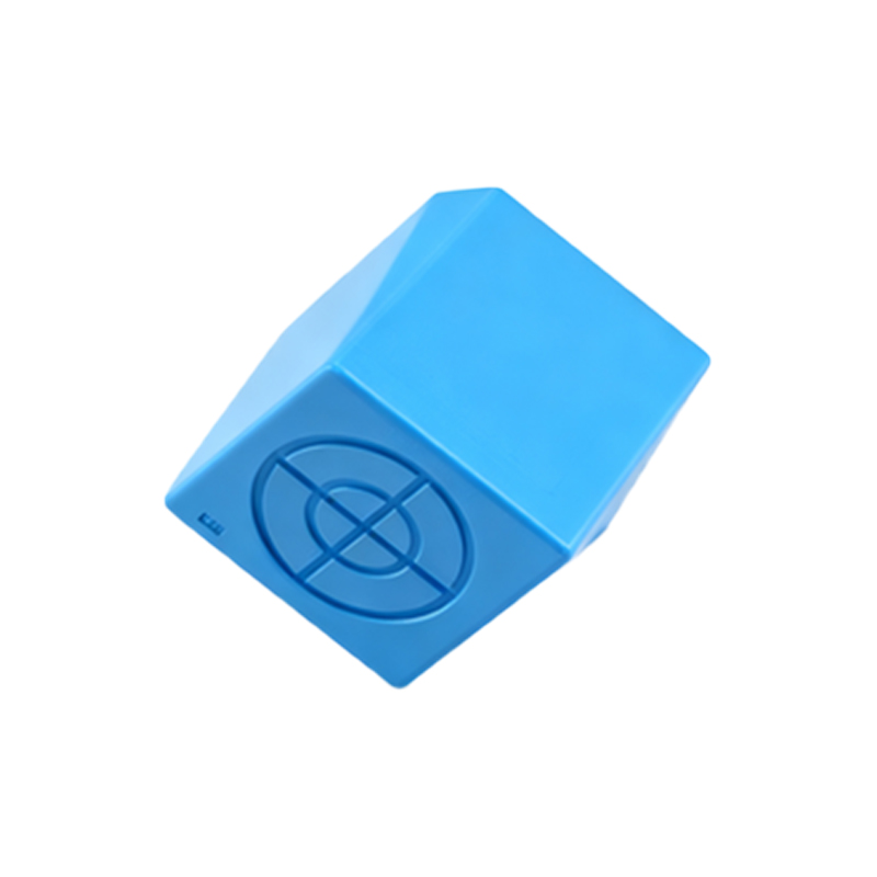
The entire electronic assembly is encapsulated within a housing, commonly constructed from nickel-plated brass, stainless steel, or high-grade engineering plastics like PBT or PPS. The housing provides an IP (Ingress Protection) rating (e.g., IP67, IP69K) against dust and water ingress. It also features a threaded barrel (e.g., M8, M12, M18, M30) or a rectangular form factor for easy mounting. The rear end contains the cable gland or a standardized quick-disconnect connector (e.g., M12 connector). Internal potting compound is often used to secure components, provide shock and vibration resistance, and improve thermal conductivity.
Structural Diagram Flow:
A standard block diagram illustrates the signal flow as follows:
Sensing Face & Coil -> High-Frequency Oscillator -> Demodulator -> Schmitt Trigger/Amplifier -> Output Switch (Transistor) -> Load.
Power supply lines run in parallel to power each stage. LEDs for power and output status indication are commonly integrated into the circuit board.
Understanding this structure allows for better sensor selection based on sensing distance, target material, switching frequency, and environmental conditions. It also aids in troubleshooting; for instance, a failed oscillator may cause a complete loss of detection, while a damaged output transistor may result in the sensor drawing current but failing to switch the load. The robust, integrated design of modern proximity sensors ensures millions of reliable operating cycles, making them a cornerstone of automated system logic and safety interlocks.