In the realm of industrial automation and control systems, proximity sensors are indispensable components for non-contact detection of objects. Among their various operational principles, the method involving adjustable resistance, often related to sensitivity or output configuration, is a critical aspect for fine-tuning sensor performance to specific application needs. This article delves into the underlying principle of this adjustable resistance mechanism, explaining its role and implementation in common proximity sensor types.
Fundamentally, a proximity sensor detects the presence or absence of an object within its sensing range without physical contact. Common technologies include inductive, capacitive, and photoelectric sensors. The concept of "adjustable resistance" in this context typically does not refer to a variable resistor directly in the sensing element's core detection circuit (like an oscillator coil in an inductive sensor). Instead, it most commonly pertains to external or integrated circuitry that allows for the adjustment of operational parameters, effectively acting as a metaphorical "resistance" to electrical signals, thereby modifying sensor behavior.
The primary application of this adjustable function is sensitivity adjustment. For instance, in an inductive proximity sensor, the sensor generates an electromagnetic field. When a metallic object enters this field, it causes eddy currents, which load the sensor's internal oscillator, leading to a change in amplitude. This change is detected and converted into a switching output. However, different metals, object sizes, or required sensing distances necessitate fine-tuning. An integrated potentiometer, accessible from the sensor housing, is often provided. This potentiometer is part of a threshold detection circuit. By adjusting its resistance, the user alters the reference voltage level at which the comparator circuit triggers the output switch. Increasing the effective resistance might raise the trigger threshold, making the sensor less sensitive (requiring a closer or larger object). Decreasing it lowers the threshold, increasing sensitivity. This adjustment compensates for application variables and prevents false triggering from background interference.
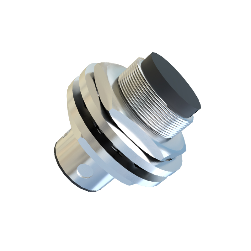
Similarly, in capacitive proximity sensors, which detect both metallic and non-metallic materials by sensing changes in capacitance, a sensitivity adjustment potentiometer is almost standard. It adjusts the threshold of the capacitance-to-voltage converter circuit, allowing the sensor to be tuned for specific materials (e.g., plastic, wood, liquid levels) and to ignore environmental factors like humidity or dust buildup on the face.
Another context for adjustable resistance involves the output stage. Some sensors, particularly analog output types (e.g., 4-20mA or 0-10V), may feature span and zero-point adjustments. These adjustments, often achieved via multi-turn potentiometers, set the minimum and maximum output signal corresponding to the sensing range. Here, the potentiometers resistances define the gain and offset of the output amplifier circuit. For example, adjusting the "span" pot changes the feedback resistance in an operational amplifier circuit, scaling the output range. While not a simple series resistor, its function is to control signal levels resistively.
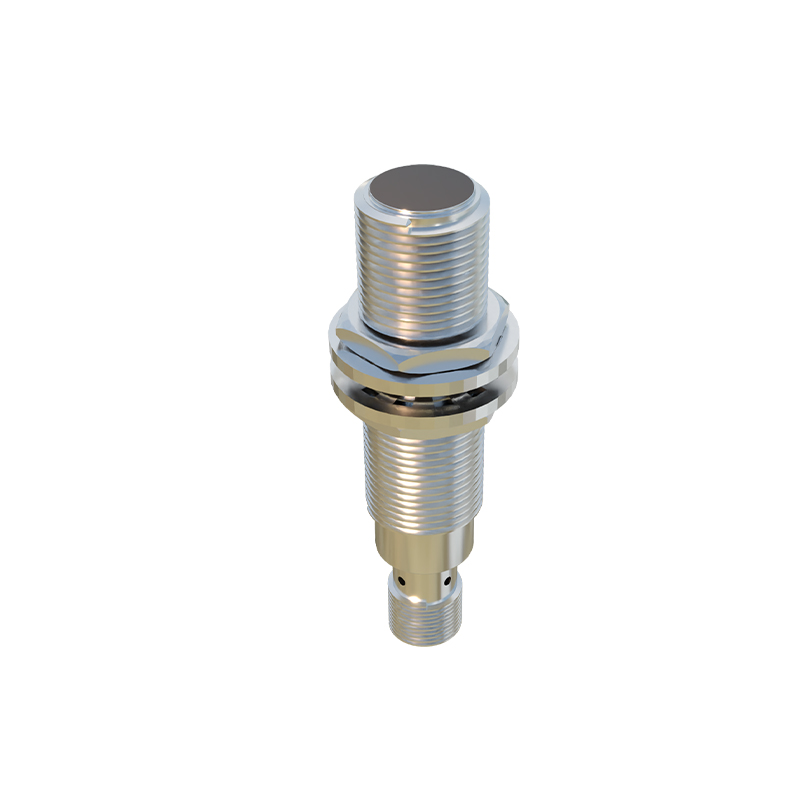
Furthermore, in certain two-wire AC/DC proximity sensors, an external adjustable resistor or potentiometer can sometimes be connected in parallel or series with the load to adjust the leakage current or minimum guaranteed load current, ensuring proper switching with low-power PLC inputs. This is a direct application of an adjustable resistor in the sensor's operational circuit.
The implementation is typically through precision potentiometers or trimmers mounted on the sensor's PCB. Manufacturers design these with robust, often sealed, adjustments to withstand industrial environments. The adjustment is usually a finite rotation (e.g., 20 turns) to allow for precise setting. It is crucial to follow the manufacturer's guidelines during adjustment, often using the provided indicator LED as a guide: turning until the LED flickers at the desired detection point and then backing off slightly for a stable operating margin.
In summary, the principle of adjustable resistance in proximity sensors is centered on providing user-configurability for sensitivity, output range, or load compatibility. It introduces a variable resistive element into the sensor's signal conditioning or output circuitry, enabling the calibration of electrical thresholds. This flexibility is key to deploying standard sensor models across diverse applications, ensuring reliable detection, optimizing performance, and reducing installation and maintenance complexity. Understanding this principle allows engineers and technicians to correctly install, tune, and troubleshoot these vital components, maximizing system efficiency and reliability.