Proximity sensor switches are indispensable components in modern industrial automation, providing non-contact detection of metallic and, in some cases, non-metallic objects. Their reliability is paramount for ensuring continuous production flow, machine safety, and process consistency. However, like all electronic devices, they are susceptible to environmental factors, electrical issues, and mechanical wear. Understanding systematic maintenance and troubleshooting methods is crucial for minimizing downtime and extending sensor lifespan. This guide outlines professional maintenance procedures for inductive and capacitive proximity sensors, the most common types in industrial settings.
The first step in any maintenance protocol is a thorough visual inspection. Power down the equipment and lock out/tag out (LOTO) the energy sources before proceeding. Examine the sensor's face for accumulations of metal chips, dust, oil, or coolant. Even a thin layer of conductive material can cause erratic switching or false triggering. Clean the sensing face gently with a soft, lint-free cloth and an appropriate solvent, such as isopropyl alcohol for general grime. Avoid abrasive materials that could scratch the housing or face. Inspect the housing for cracks, dents, or signs of impact that could compromise the IP (Ingress Protection) rating, leading to moisture or particulate ingress. Check the cable and cable entry point for cuts, abrasions, or tight bends that may have damaged the internal wiring.
Electrical verification is the core of functional diagnostics. After ensuring safe access, re-energize the circuit. Use a reliable digital multimeter to measure the supply voltage at the sensor's terminals or connector. Ensure it matches the sensor's specified range (e.g., 10-30V DC). An unstable or low voltage often points to a power supply issue rather than a sensor fault. Next, monitor the output signal. For a DC 3-wire sensor, connect the meter between the output wire (typically black or blue) and the negative supply. In the absence of a target, the output should be in its normal state (OFF for normally open sensors). When a standard target (usually a square of mild steel specified by the manufacturer) is brought within the rated sensing distance, the output should switch. The voltage should change close to the supply voltage (for a PNP sourcing sensor) or near 0V (for an NPN sinking sensor). A significant voltage drop under load may indicate a failing output transistor.
Environmental factors are frequent culprits. Inductive sensors can be influenced by adjacent metal structures, other sensors, or large magnetic fields. Ensure the sensor is mounted with adequate clearance from surrounding metal as per its installation guidelines. "Cross-talk" between closely mounted sensors can sometimes be resolved by switching them to opposite operating frequencies, if the model supports it. For capacitive sensors, changes in humidity, material composition, or the presence of dust/foam on the face can drastically alter the sensing characteristics. Readjust the sensitivity potentiometer if available, and ensure the sensor is calibrated for the specific material it is detecting.
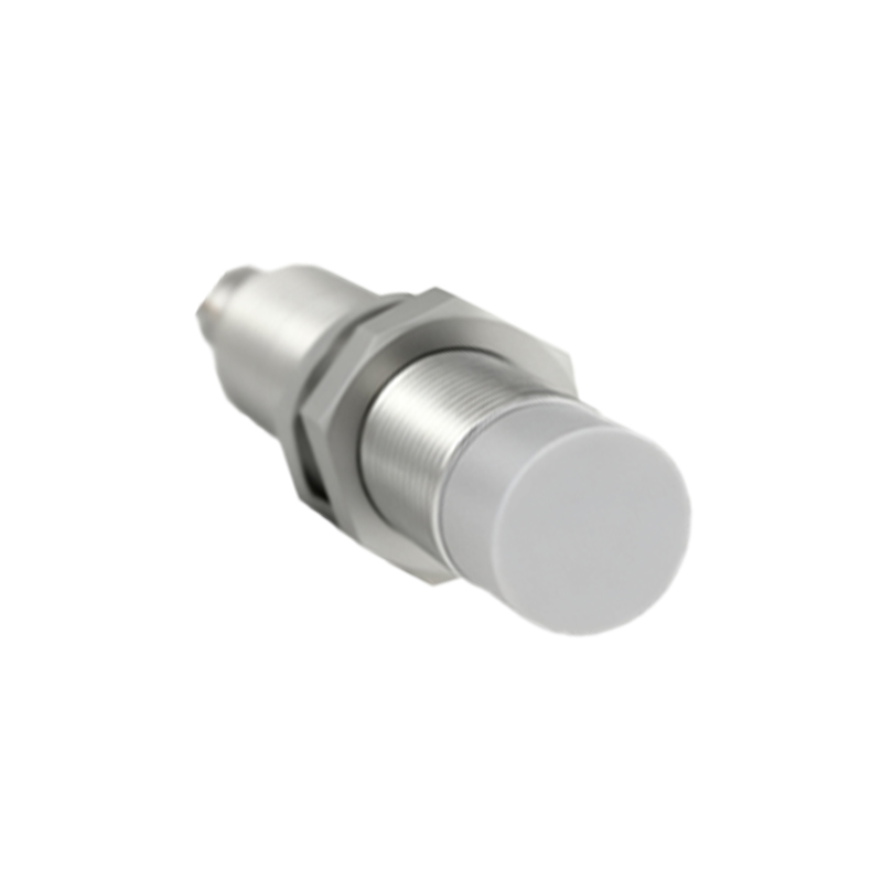
If the sensor fails electrical tests, replacement is often the most cost-effective solution given the high reliability and sealed nature of modern units. However, before replacement, double-check the wiring against the datasheet diagram. Common wiring errors include confusing PNP and NPN types, incorrect load connection, or mixing up the supply lines. Also, verify the load (e.g., PLC input, relay coil) is functioning correctly and its impedance is within the sensor's switching capacity. A short circuit in the load can damage the sensor's output stage.
Preventive maintenance schedules are key. Establish regular intervals for cleaning and inspection based on the operational environment. Harsh environments with excessive conductive dust, welding spatter, or high-pressure washdown require more frequent checks. Consider using sensors with higher IP ratings (e.g., IP67, IP69K) and specialized housings (stainless steel) for such areas. Logging performance data and failure modes can help identify systemic issues, such as recurring vibration-induced failures, prompting a review of mounting methods or the use of vibration-resistant models.
In summary, effective proximity sensor maintenance hinges on a methodical approach: Safety first, followed by visual inspection, electrical verification, environmental assessment, and systematic replacement. By integrating these practices into routine maintenance schedules, engineers and technicians can ensure optimal performance, enhance system reliability, and avoid costly unplanned production stoppages. Always consult the manufacturer's specific documentation for detailed specifications, sensing curves, and special instructions.