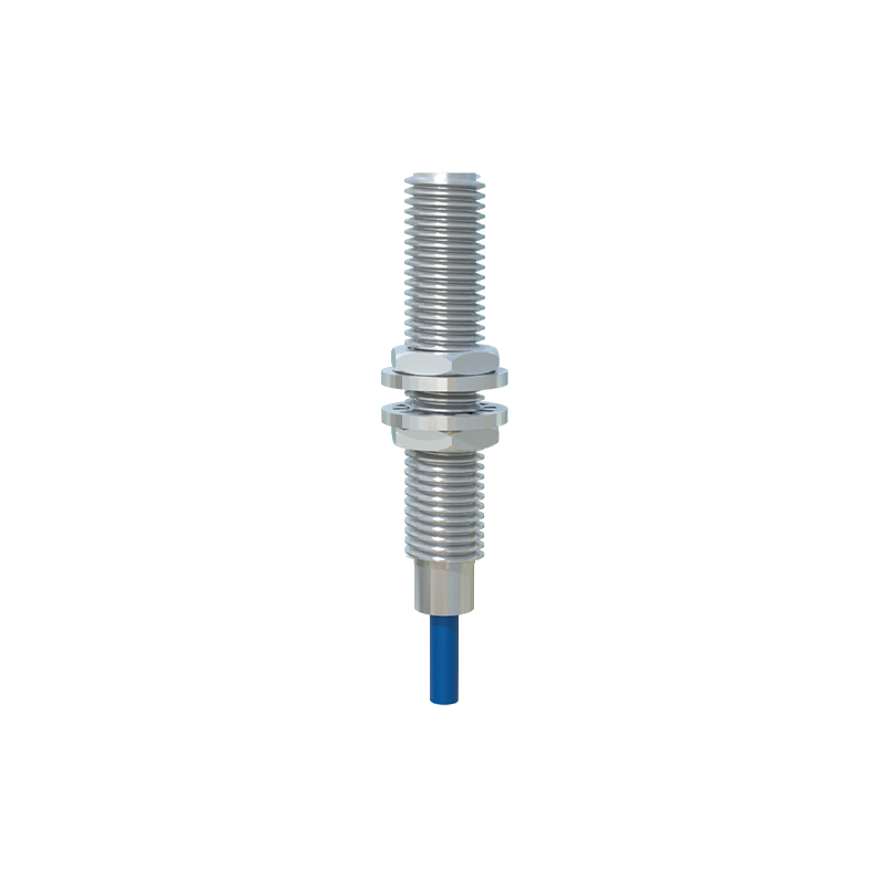
In industrial automation and control systems, proximity sensors are indispensable components for detecting the presence or absence of objects without physical contact. However, their reliable operation is frequently compromised by electromagnetic interference (EMI), leading to false triggering, reduced sensing range, or complete operational failure. Eliminating this interference is a critical engineering challenge. This guide provides a systematic, practical approach to identifying and mitigating interference issues in inductive, capacitive, and photoelectric proximity sensors.
The first and most crucial step is accurate diagnosis. Interference symptoms often manifest as erratic behavior. A sensor might trigger without a target present, fail to detect a valid target, or exhibit a fluctuating output signal. To confirm EMI as the culprit, begin with a process of elimination. Check all mechanical connections, mounting stability, and the physical condition of the sensor face. Ensure the target material, size, and approach are within the sensor's specified parameters. Once mechanical and application errors are ruled out, investigate the electrical environment. Use an oscilloscope to monitor the sensor's output line and power supply lines for noise spikes or irregularities that correlate with the malfunction. Common sources of interference include variable frequency drives (VFDs), large motors, welding equipment, radio transmitters, and other sensors operating on similar frequencies. Pay close attention to the installation environment; running sensor cables in parallel with high-current AC power lines is a typical cause of induced noise.
With the source identified, implement mitigation strategies, starting with proper sensor selection and installation. Choose a sensor with a robust metal housing, as it provides inherent shielding. For areas with extreme EMI, select models explicitly designed with enhanced noise immunity. During installation, maintain maximum practical distance between sensor cables and potential noise sources. A minimum separation of 20-30 cm from power cables is a good rule of thumb. Avoid running cables in parallel with noisy lines; cross them at right angles if they must intersect. Secure cables using grounded metallic cable trays or conduits, which act as a Faraday cage, containing radiated emissions from the cable and shielding it from external fields. Ensure all metal conduits and trays are properly grounded at a single point to avoid ground loops.
Wiring practices are paramount. Always use shielded cables for sensor connections. The shield must be composed of a braided copper or aluminum foil with a drain wire. Crucially, connect the cable shield to ground at only one end—typically at the controller or power supply end. Grounding both ends can create a ground loop, which is a primary path for circulating noise currents. Keep sensor lead wires as short as possible to reduce their effectiveness as antennas. For DC sensors, incorporate filtering directly at the sensor or the load. A bypass capacitor (e.g., 0.1 µF) connected across the power supply terminals of the sensor can suppress high-frequency noise. For the output signal line, an RC filter (a resistor and capacitor in series to ground) can smooth out transient spikes. Many modern programmable logic controllers (PLCs) and input cards also feature configurable digital filtering that can ignore brief signal pulses.
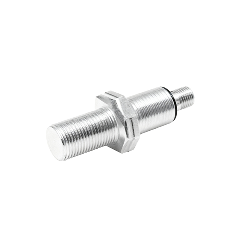
For systems powered by AC, consider using a line filter or an isolation transformer to clean the incoming power supply, preventing conducted interference from propagating through the system. In scenarios with multiple sensors, especially capacitive ones, mutual interference can occur. Stagger the installation or use sensors with synchronization capabilities (like a "Sync" input) that allows them to operate on alternating cycles, preventing them from emitting and receiving each other's signals. For photoelectric sensors, ensure the lens is clean and protected from ambient light sources like sunlight or strobe lights, which are forms of optical interference. Using a modulated LED light source and a receiver tuned to the same frequency greatly enhances immunity to ambient light.
Finally, establish a robust and clean grounding system. This is often the most overlooked yet vital aspect. The grounding point for the sensor system should be a dedicated, low-impedance earth ground, separate from the noisy ground connections of high-power equipment. Use star-point grounding where feasible to prevent ground loops. Regularly inspect ground connections for corrosion or looseness.
In conclusion, eliminating proximity sensor interference is not a single-action fix but a holistic approach involving careful selection, disciplined installation, meticulous wiring, and strategic filtering. By systematically diagnosing the noise source and applying these layered defensive measures, engineers can ensure the high reliability and precision that modern automated systems demand. Persistent problems may require consulting the sensor manufacturer's application notes, as they often provide model-specific guidance for challenging environments.