In the realm of automotive and industrial vehicle systems, the accurate measurement of rotational speed is paramount for functions ranging from anti-lock braking systems (ABS) and traction control to transmission management and speedometer operation. At the heart of this critical data acquisition lies the proximity switch, a robust and reliable type of sensor commonly employed as a vehicle speed sensor (VSS). This article delves into the operational principles, key types, design considerations, and application best practices for proximity switches used in speed sensing.
Fundamentally, a proximity switch is a non-contact sensor that detects the presence or absence of a metallic target without physical contact. When configured as a speed sensor, it typically faces a toothed reluctor wheel (or tone ring) attached to a rotating shaft, such as a wheel hub, transmission output shaft, or crankshaft. The core operating principle is based on electromagnetic induction or the eddy current effect. An active sensor contains an oscillator circuit that generates a high-frequency electromagnetic field at its sensing face. When a tooth of the reluctor wheel passes through this field, eddy currents are induced in the metal, causing a measurable change in the oscillator's amplitude or frequency. This change is processed by internal circuitry to produce a clean, digital output signal—typically a square wave—where the frequency of the pulses is directly proportional to the rotational speed of the target.
Two primary types of proximity switches dominate VSS applications: inductive and active Hall-effect sensors. Inductive proximity sensors are passive devices, generating their signal purely from the change in magnetic reluctance as the ferrous target passes. They are renowned for their simplicity, durability, and ability to operate in harsh environments without an external power supply for basic versions, though active two-wire versions are common. However, they have a minimum speed threshold (typically around 1 Hz) below which they cannot generate a reliable signal. In contrast, active Hall-effect sensors incorporate an integrated circuit that detects changes in magnetic field strength. They require an external power supply but offer significant advantages: they can detect static (zero-speed) presence of a target, provide a more precise digital output with sharper edges, and are generally less sensitive to air gap variations between the sensor and the target wheel. Modern Hall-effect sensors are often the preferred choice for modern automotive applications demanding high accuracy across the entire speed range.
Several critical engineering parameters must be meticulously specified during the design-in phase. The air gap, or the distance between the sensor face and the target, is crucial and must remain within the sensor's specified limits under all thermal and vibrational conditions. The target geometry—including tooth size, shape, pitch, and material (ferrous steel is standard)—directly influences signal strength and integrity. Engineers must also consider the output configuration: PNP vs. NPN sourcing, current sinking, or specific protocols like a two-wire variable reluctance sensor with a sinusoidal output. Environmental resilience is non-negotiable; the sensor must withstand extreme temperatures (-40°C to +150°C is typical), exposure to contaminants like oil, grease, and road salt, and high levels of vibration and shock. Proper sealing to IP67 or IP69K standards is often required.
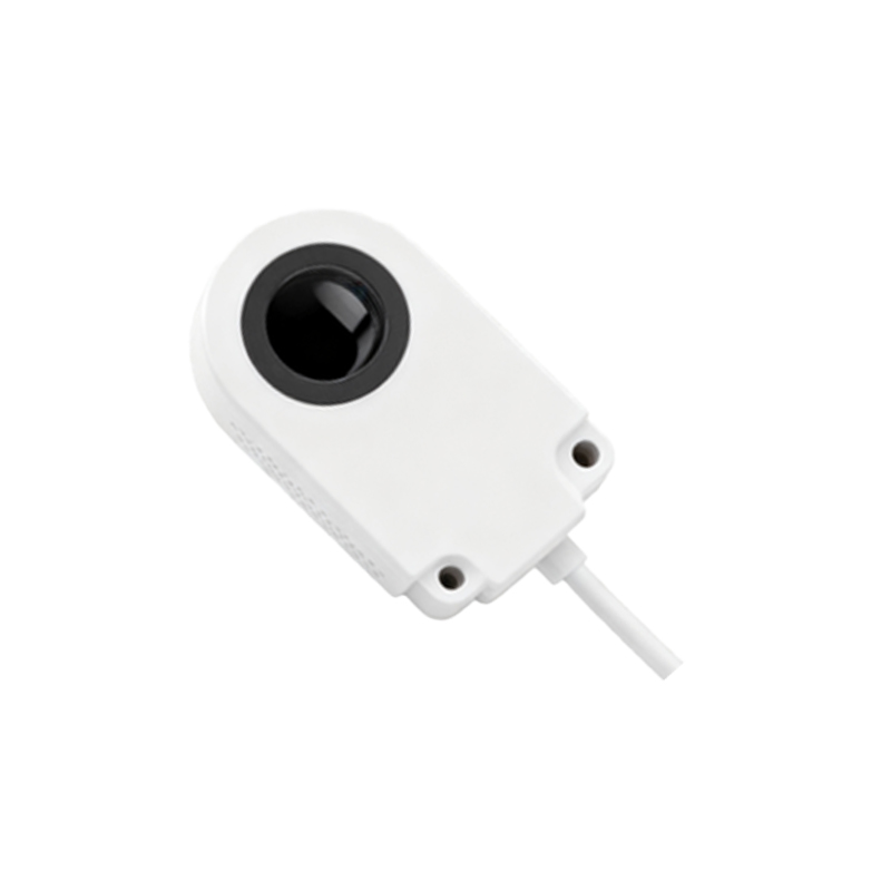
Installation and integration are as vital as sensor selection. Proper alignment perpendicular to the target wheel is essential to ensure consistent signal amplitude across all teeth. Shielding of the signal cable is mandatory to protect the low-voltage output from electromagnetic interference (EMI) generated by ignition systems, motors, or other power electronics. Signal conditioning, sometimes integrated into the sensor itself or handled by the Engine Control Unit (ECU), involves converting the raw signal into a clean, debounced digital pulse train. Diagnostics, such as detecting open or short circuits, are increasingly built into smart sensor ICs.
In application, these sensors feed real-time speed data to various vehicle control modules. For ABS, the ECU compares the speed of individual wheels; a rapid deceleration in one signal indicates potential lock-up, triggering brake pressure modulation. In automatic transmissions, shift points are precisely timed based on vehicle speed and engine load. The proliferation of advanced driver-assistance systems (ADAS) like adaptive cruise control and electronic stability control has further elevated the importance of reliable, high-fidelity speed data from these robust proximity switches.
Looking forward, trends point towards the integration of more intelligence into the sensor package, including self-diagnostic features and digital bus output (e.g., SENT or PSI5 protocols) for reduced wiring and enhanced data integrity. However, the fundamental role of the electromagnetic proximity switch as a workhorse for rotational speed sensing remains unchallenged. Its combination of mechanical simplicity, proven reliability in demanding conditions, and cost-effectiveness ensures its continued prevalence in vehicle systems for the foreseeable future. Mastery of its characteristics and application nuances is a fundamental competency for engineers designing motion control and safety