Capacitive proximity sensors are widely used in industrial automation for non-contact detection of various objects, including metals, plastics, liquids, and granular materials. Unlike inductive sensors, which only detect metallic objects, capacitive sensors operate by generating an electrostatic field and detecting changes in capacitance when an object enters this field. This teardown analysis provides an in-depth look at the internal components, working principles, and design considerations of a typical industrial-grade capacitive proximity sensor.
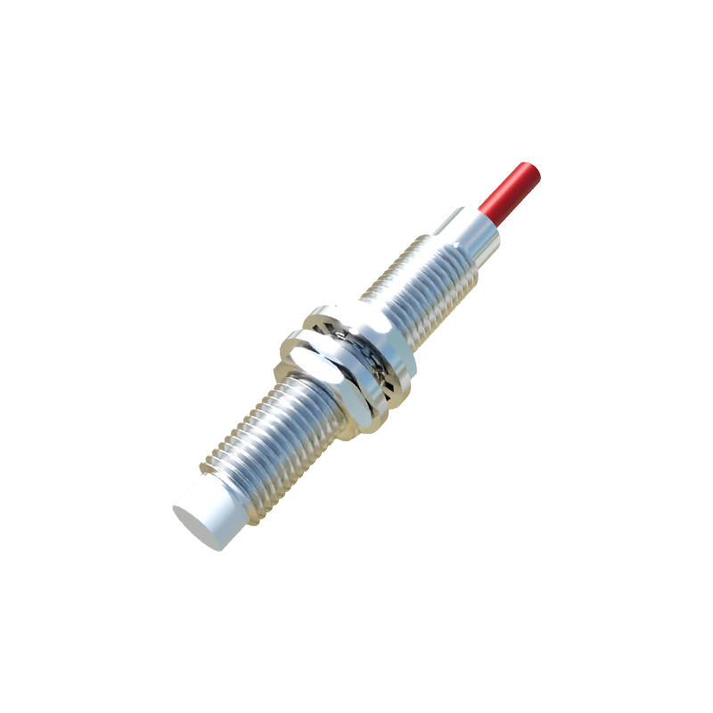
The sensor under examination is a cylindrical model with an M18 threaded housing, rated for 10-30V DC operation and featuring a PNP normally open output. The housing is constructed from stainless steel, providing durability and resistance to environmental factors such as moisture, dust, and chemical exposure. The sensing face is made of a polymer material that allows the electrostatic field to penetrate while protecting the internal electronics.
Upon disassembling the sensor, the internal structure reveals several key components. The core of the sensor is a capacitive sensing electrode, typically a conductive plate or ring connected to an oscillator circuit. This electrode generates a low-power electrostatic field that extends beyond the sensor's face. When an object enters this field, it alters the dielectric properties, causing a change in capacitance. This change is detected by the oscillator circuit, which then triggers the output switching mechanism.
The oscillator circuit is built around a specialized integrated circuit (IC) designed for capacitive sensing applications. This IC includes a high-frequency oscillator, a signal conditioning stage, and a comparator. The oscillator generates a stable frequency that shifts when capacitance changes. The signal conditioning stage amplifies and filters this signal, while the comparator determines whether the change exceeds a predefined threshold, activating the output.
Adjacent to the IC is the output stage, which consists of a transistor (in this case, a PNP type) and protection components such as diodes and resistors. The transistor switches the load connected to the sensor's output terminal. Protection diodes guard against reverse polarity and voltage spikes, ensuring reliable operation in harsh industrial environments. The sensor also includes an LED indicator that lights up when an object is detected, providing visual feedback for troubleshooting.
Power regulation is handled by a small voltage regulator circuit that ensures stable operation across the specified voltage range. This is critical for maintaining consistent sensing performance despite fluctuations in the supply voltage. The regulator steps down the input voltage to a level suitable for the IC and other components, typically 5V or 3.3V.
The sensing electrode is carefully insulated from the housing to prevent false triggers caused by the sensor's own metal body. This insulation is achieved using a non-conductive potting material that fills the space between the electrode and the housing. The potting material also provides mechanical stability and protects the internal components from vibration and shock.
One notable design feature is the adjustable sensitivity potentiometer, accessible through a small hole in the housing. This potentiometer allows users to fine-tune the sensor's detection range, compensating for different material properties or environmental conditions. Turning the potentiometer adjusts the reference voltage of the comparator, effectively changing the capacitance threshold required for activation.
In terms of performance, capacitive proximity sensors offer several advantages. They can detect non-metallic objects, making them versatile for applications like level sensing in tanks or presence detection of plastic parts. However, they are also sensitive to environmental factors such as humidity and temperature, which can affect the dielectric constant of the air and lead to drift. To mitigate this, high-quality sensors incorporate temperature compensation circuits and use stable dielectric materials.
The teardown also highlights common failure points. Over time, the potting material may degrade, leading to moisture ingress and circuit failure. The sensing face can become contaminated with dust or oil, reducing sensitivity. Regular maintenance, including cleaning and calibration, is recommended to ensure long-term reliability.
In conclusion, capacitive proximity sensors are sophisticated devices that combine principles of electrostatics with advanced electronics. Their ability to detect a wide range of materials makes them indispensable in modern automation. This teardown reveals the careful engineering behind their robust performance, from the shielded electrode to the protected output stage. Understanding these internal details can aid in proper selection, installation, and troubleshooting, ultimately enhancing system efficiency and uptime.