Proximity sensors are indispensable components in modern industrial automation, providing non-contact detection of objects with high reliability and speed. However, like any precision instrument, their performance can drift over time due to environmental factors, mechanical wear, or component aging. Proper calibration is therefore critical to ensure accurate detection, prevent false triggers, and maintain system integrity. This guide outlines a systematic, best-practice approach to calibrating inductive, capacitive, and ultrasonic proximity sensors commonly used in manufacturing and process control.
Before initiating any calibration procedure, safety must be the paramount concern. Always follow Lockout-Tagout (LOTO) protocols to isolate the machine or system from all energy sources. Verify the system is in a safe state and that personnel are clear of any potential hazards. Gather the necessary tools: the sensor's datasheet, a set of certified calibration targets (typically the specified material, such as mild steel for inductive sensors), feeler gauges, a stable power supply matching the sensor's specifications, and a high-quality digital multimeter or oscilloscope for signal measurement.
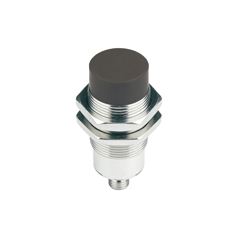
The calibration process begins with a thorough visual inspection. Check the sensor's housing for cracks, corrosion, or physical damage. Ensure the sensing face is clean and free from debris, grease, or metal shavings that could attenuate the signal. Verify the electrical connections are secure and the cabling is undamaged. Any compromise in physical condition can render calibration ineffective.
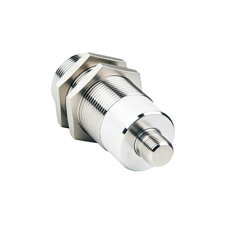
Next, reference the manufacturer's datasheet to confirm the sensor's key specifications: nominal sensing distance (Sn), operating voltage range, output type (PNP/NPN, analog, or IO-Link), and the recommended target material and size. The sensing distance is typically defined for a standard target. It's crucial to use the correct target during calibration, as using an undersized or different material target will yield inaccurate results.
For standard two-wire or three-wire DC sensors with a discrete output, the primary calibration adjustment is often the sensing distance or the hysteresis setting. Power the sensor according to its specifications. Using the certified target, slowly bring it axially toward the sensing face. Observe the point at which the output switches state (e.g., from OFF to ON for a normally-open sensor). This is the actual "operating point." Measure this distance carefully using calipers or a precision gauge. Compare this measured distance to the nominal sensing distance (Sn) from the datasheet. Most industrial-grade sensors allow for a tolerance, often ±10%. If the deviation exceeds the acceptable tolerance, adjustment is needed.
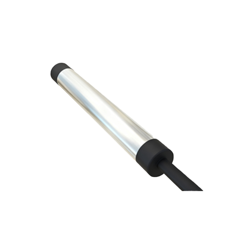
Many modern sensors feature a potentiometer or are configurable via software for sensitivity adjustment. To calibrate, place the target at the exact required nominal sensing distance. For a potentiometer-based sensor, use a non-metallic screwdriver to adjust the potentiometer until the output state just changes. Make fine adjustments, moving the target slightly in and out to find the precise threshold. For sensors with teach-in functionality (common in analog and IO-Link devices), follow the manufacturer's procedure, which usually involves pressing a button or sending a command to set the switch point at the current target distance.
For analog output sensors, calibration involves verifying the output curve. You will need to measure the output current (e.g., 4-20mA) or voltage (e.g., 0-10V) at multiple known distances. Plot these points against the distance to ensure linearity and that the output spans the full specified range. Use the sensor's trim pots or configuration software to adjust the zero (or offset) and span (or gain) if the readings are out of specification.
Environmental compensation is a vital, often overlooked step. Factors like temperature, humidity, and adjacent metal can affect performance. If possible, perform a final check under the sensor's actual operating conditions. For instance, run the machine until it reaches normal operating temperature and verify the sensor's trigger point remains stable.
Documentation is the final, critical step. Record the as-found condition (measurements before calibration) and the as-left condition (measurements after calibration). Note the date, tool used, technician, sensor model, serial number, and any environmental conditions. This creates an audit trail for predictive maintenance and helps identify sensors that may be failing prematurely.
Regular calibration should be part of a preventive maintenance schedule. The interval depends on the application's criticality and the operating environment—harsh environments with vibration, temperature swings, or contaminants necessitate more frequent checks. A well-calibrated proximity sensor ensures not only operational efficiency but also contributes significantly to the safety and quality of the automated process. By adhering to these methodical steps, engineers and technicians can maintain the high level of precision that modern industrial systems demand.