In industrial automation and control systems, proximity sensors play a critical role in non-contact detection of metallic or non-metallic objects. Among various wiring configurations, the 2-wire proximity sensor is widely adopted due to its simplicity and cost-effectiveness. This article provides a comprehensive guide to the 2-wire connection method, complete with diagrams and practical considerations for engineers and technicians.
A 2-wire proximity sensor integrates both power supply and signal output into a single pair of wires, simplifying installation and reducing wiring complexity. Unlike 3-wire or 4-wire sensors that have separate power, ground, and signal lines, the 2-wire version operates in series with the load. When the sensor detects a target, it switches its internal circuit to allow current flow, activating the connected device such as a PLC input, relay, or indicator.
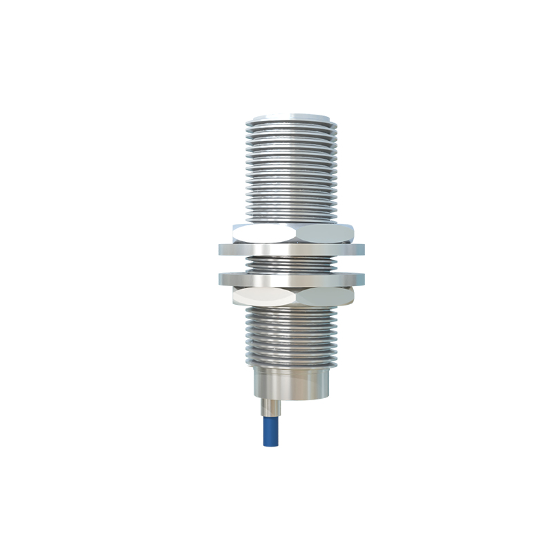
Basic Wiring Diagram and Principle
The standard wiring setup involves connecting one wire to the positive DC supply voltage (typically 10-30 VDC) and the other wire to the load, which then returns to the negative side of the power supply. Here’s a step-by-step breakdown:
1. Power Supply Connection: Connect the positive terminal of the DC power source to one wire of the sensor. Ensure the voltage matches the sensor’s rated operating range (e.g., 12-24 VDC).
2. Load Connection: Link the sensor’s second wire to one terminal of the load (e.g., a PLC digital input module or relay coil).
3. Return Path: Connect the other terminal of the load to the negative side of the power supply, completing the circuit.
A typical diagram shows:
DC Power Supply (+) → Wire 1 → Proximity Sensor → Wire 2 → Load → DC Power Supply (-).
When no target is present, the sensor maintains a high impedance state, allowing minimal leakage current (usually under 1 mA) to prevent accidental load activation. Upon detection, the impedance drops significantly, enabling sufficient current to drive the load. This behavior is akin to a switch closing in series with the load.
Key Considerations for Reliable Operation
1. Load Compatibility: Verify that the load’s operating current falls within the sensor’s rated switching capacity. Exceeding the maximum current can damage the sensor, while insufficient current may cause unreliable switching. Most 2-wire sensors support loads from 5 mA to 200 mA.
2. Leakage Current: In the “off” state, a small leakage current flows through the sensor. If the load has a low minimum operating current (e.g., some PLC inputs), this leakage might falsely trigger the load. To mitigate this, connect a bypass resistor in parallel with the load to shunt excess current. Calculate the resistor value using Ohm’s law based on the sensor’s leakage current specification.
3. Voltage Drop: Since the sensor carries the load current, an internal voltage drop occurs (typically 1.5-3 V). Ensure the residual voltage at the load meets its operational requirements. For instance, with a 24 VDC supply and a 2 V sensor drop, the load receives 22 VDC.
4. Wiring Practices: Use shielded cables in electrically noisy environments to prevent interference. Keep sensor cables away from high-voltage lines and motors. Adhere to color-coding standards (e.g., brown for positive, blue for negative) where applicable.
5. Sensor Types: Both NPN (sinking) and PNP (sourcing) 2-wire variants exist, though NPN is more common. Confirm the sensor’s output logic matches the load’s expectations. For DC circuits, ensure correct polarity to avoid reverse-voltage damage.
Application Examples
- PLC Integration: Connect the sensor directly to a PLC digital input. The PLC’s internal circuitry acts as the load. Check the PLC input module’s specifications for compatibility with 2-wire sensors.
- Relay Control: Wire the sensor to control a relay coil. The relay then switches higher-power devices like motors or solenoids. Include a flyback diode across the coil to suppress voltage spikes.
- Indicator Lights: Drive LED indicators for visual status monitoring. Series resistors may be needed to limit current to the LED’s rated value.
Troubleshooting Tips
- No Response: Measure voltage across the load. If near zero, check for open circuits or incorrect wiring. Verify the sensor is powered within its voltage range.
- False Triggering: Assess leakage current using a multimeter. Install a bypass resistor if necessary. Inspect for environmental factors like metal debris or electromagnetic interference.
- Inconsistent Detection: Ensure the target material and size