Proximity sensors are indispensable components in modern industrial automation, providing non-contact detection of metallic and, in some cases, non-metallic objects. Understanding their wiring is fundamental for correct installation, troubleshooting, and system integration. This guide provides a detailed explanation of standard proximity sensor wiring diagrams, focusing on the prevalent 3-wire DC configurations.
At its core, a proximity sensor consists of an oscillator, a detection coil, a signal amplifier, and an output circuit. The wiring diagram visually represents how these internal components connect to an external power source and a load, such as a Programmable Logic Controller (PLC) input, a relay, or an indicator lamp. The most critical distinction in wiring is between the two primary output types: NPN (sinking) and PNP (sourcing). This terminology refers to the type of transistor used in the sensor's output stage.
Let's begin with a 3-wire DC PNP (Sourcing) Sensor. A PNP sensor sources current to the load. In a standard wiring diagram, you will identify three wires, typically color-coded as Brown, Blue, and Black (though colors can vary by manufacturer; always consult the datasheet). The Brown wire connects to the positive DC supply voltage (e.g., +24VDC). The Blue wire connects to the negative DC supply voltage, or 0V (common). The Black wire is the output signal wire. In the PNP configuration, when the sensor detects a target, it switches the internal PNP transistor, connecting the Black output wire to the internal positive supply. This effectively "sources" positive voltage from the sensor to the load. The load (e.g., a PLC digital input) is then connected between the Black wire (signal) and the Blue wire (0V). Current flows from the sensor's output, through the load, and to the common (0V).
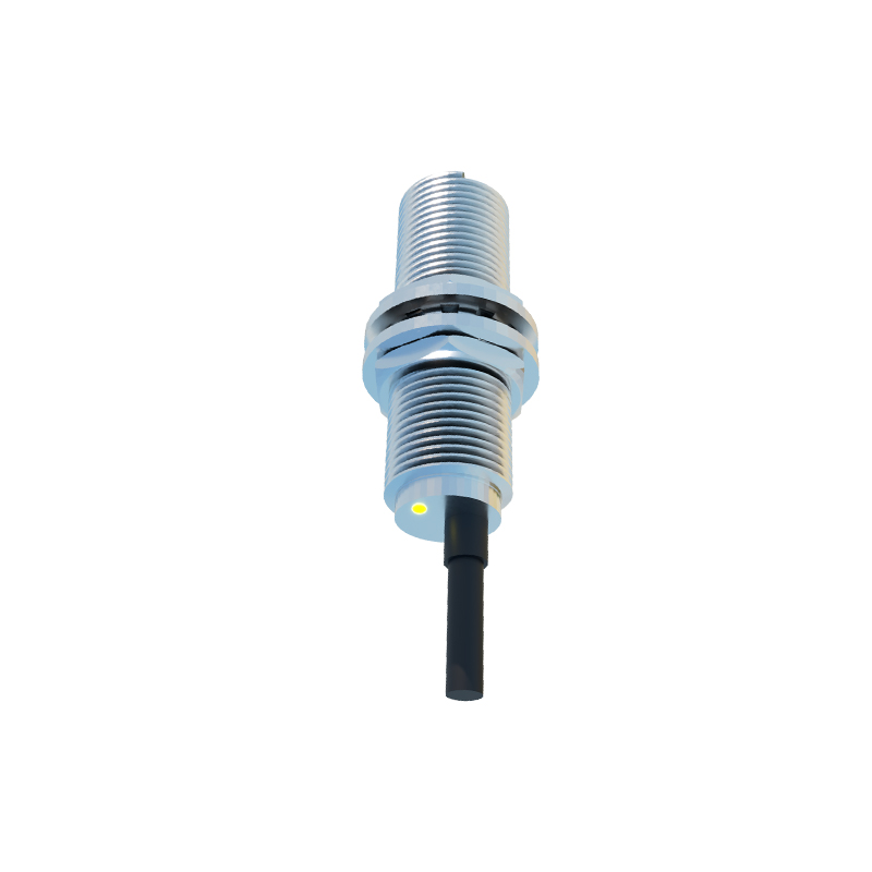
Conversely, a 3-wire DC NPN (Sinking) Sensor sinks current from the load. The power connections remain identical: Brown to positive (+V), Blue to negative or common (0V). The critical difference is the function of the Black output wire. In an NPN sensor, the internal NPN transistor connects the Black wire to the internal common (0V) when activated. Therefore, the load must be connected between the positive supply (+V) and the Black output wire. When the sensor detects a target, it completes the circuit by allowing current to flow from the positive supply, through the load, and into the sensor's output, which then sinks it to 0V. A simple way to remember is: PNP = Positive switched, NPN = Negative switched.
A standard wiring diagram will also include symbols for protective devices. A reverse polarity protection diode is often integrated to prevent damage if the Brown and Blue wires are accidentally swapped. Short-circuit protection is another common feature, safeguarding the output transistor. Some sensors include a built-in LED status indicator; its connection is internally derived from the power lines. The diagram may show this LED in parallel with the sensing circuit.
For 2-wire DC sensors, the wiring is simpler but requires careful consideration. These sensors have only two wires, acting like a switch in series with the power supply and the load. They can be connected in a similar manner to a mechanical limit switch. However, they have a residual leakage current (even when "off") and a voltage drop when "on," which must be compatible with the load's minimum operating current and voltage requirements. Incorrect load matching can lead to malfunction.
When integrating with a PLC, the choice between PNP and NPN is dictated by the PLC input module's design. Many PLCs accept both types, but the common practice in Europe and many regions is to use PNP sensors with sinking PLC inputs (the PLC input connects the sensor to common), while NPN is more common in some Asian markets. Always verify the PLC manual. The wiring diagram for PLC connection explicitly shows the sensor's output wire connecting to the designated PLC input terminal (e.g., I0.0), with the PLC's common terminal connected appropriately to complete the circuit.
Shielded cables are recommended for longer runs or in electrically noisy environments. The wiring diagram typically denotes the cable shield, which should be grounded at only one end (usually at the control panel), not at the sensor housing, to prevent ground loops.
In summary, correctly interpreting a proximity sensor wiring diagram hinges on identifying the output type (PNP/NPN), connecting the power supply polarity correctly, and placing the load in the proper leg of the circuit. A PNP sensor sources current to a load connected to common, while an NPN sensor sinks current from a load connected to positive. Adhering to the manufacturer's diagram