Installing a laser sensor correctly is critical for ensuring reliable performance in industrial automation, quality control, and safety systems. As an experienced electrical engineer, I will guide you through a comprehensive, professional procedure. This guide assumes you have a basic understanding of electrical systems and safety protocols. Always prioritize safety: disconnect all power sources before beginning any installation work and consult the sensor's specific datasheet and manual, as details can vary between models and manufacturers.
Phase 1: Pre-Installation Planning & Site Assessment
Before mounting the sensor, thorough planning is essential. First, clearly define the application. Is it for precise distance measurement, object detection, edge positioning, or thickness monitoring? This determines the required sensor type (e.g., through-beam, retro-reflective, diffuse reflective) and specifications like sensing range, resolution, response time, and output type (PNP/NPN analog, digital IO, IO-Link, Profinet).
Conduct a detailed site assessment. Evaluate the environmental conditions: ambient temperature, potential exposure to dust, moisture, oils, or chemicals (requiring an appropriate IP rating), and the level of ambient light. Strong ambient light, especially from other lasers or sunlight, can interfere with the sensor's receiver. Note the presence of vibration or shock, which may necessitate a robust housing or vibration-dampening mount.
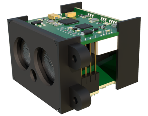
Identify the optimal mounting location. Ensure a clear, unobstructed line of sight between the sensor and the target. Consider the target's properties—its color, material, surface finish (matte vs. glossy), and size. Highly reflective or dark absorbent surfaces can affect the return signal strength in diffuse sensors. For through-beam sensors, precisely align the emitter and receiver. Verify that the mounting structure is stable and provides easy access for wiring and future maintenance.
Phase 2: Mechanical Mounting & Alignment
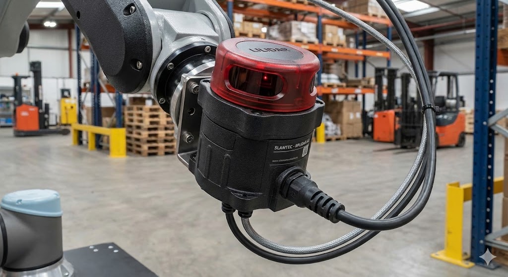
Secure the sensor using the recommended hardware (brackets, bolts, etc.). For precise alignment, use adjustable mounting brackets. Avoid overtightening, as this can distort the housing and affect accuracy.
For Through-Beam Sensors: Mount the emitter and receiver units on opposite sides of the detection area. Use an alignment tool if provided. A preliminary method is to temporarily power the receiver; its alignment indicator (often an LED) will show signal strength. Carefully adjust both units until the indicator confirms optimal alignment. Secure the units firmly.
For Reflective Sensors (Retro-reflective or Diffuse): Mount the single sensor unit. For retro-reflective types, ensure the reflector is mounted squarely opposite the sensor and is clean. For diffuse types, the sensor must be aimed directly at the expected target position. Many sensors have a built-in visible red "spot" laser for easier aiming. Activate this feature (often via a teach-button or configuration mode) to project the beam onto the target area and fine-tune the sensor's direction.
Phase 3: Electrical Wiring & Connection
Wiring must conform to local electrical codes and standards (e.g., NEC, IEC). Identify the sensor's pinout from its label or manual. Typical connections include:
* Power Supply (V+/L+ and V-/L- or COM): Connect to a stable DC power source (commonly 10-30V DC). Ensure the voltage matches the sensor's specification. Use a fused power supply for protection.
* Output Signal: Connect the output wire(s) to your controller (PLC, relay, etc.). For a digital PNP sensor (sourcing), the output provides positive voltage to the load. For an NPN sensor (sinking), it provides a path to ground. Connect analog outputs (0-10V, 4-20mA) to the appropriate analog input card.
* IO-Link/Fieldbus: For smart sensors, connect the multi-purpose port to an IO-Link master or fieldbus node according to the communication wiring diagram.
Use shielded cables in electrically noisy environments. Connect the cable shield to a functional earth ground at the control panel end only, avoiding ground loops. Ensure all connections are tight and use strain relief on the cable gland to prevent wire pull-out.
Phase 4: Configuration, Calibration & Testing
After wiring, apply power. Most sensors have status LEDs (power, output, alignment). Observe these indicators.
Now, configure the operating parameters. Basic sensors may have a teach-button or potentiometers for setting the sensing distance threshold or sensitivity. Press the teach-button when the target is in the desired "detect" state. For more advanced sensors, use the manufacturer's configuration software via a USB port, Bluetooth, or the IO-Link interface to set parameters like hysteresis, response delay, output logic (light/dark on), and filtering.
Perform a comprehensive functional test. Introduce the target object under real or simulated operating conditions. Verify the sensor triggers consistently at the correct position. Test edge cases and potential false triggers. For measuring sensors, check the output signal (voltage/current) against a known reference distance using calibrated gauges.
Phase 5: Final Validation & Documentation
Once testing is satisfactory, conduct a final validation under full operational conditions. Run the machinery or process at normal speed for an extended period, monitoring the sensor's performance. Check for any drift in calibration due to temperature changes or vibration.
Document the installation thoroughly. Record the sensor model, serial number, installation date, location, configured parameters, wiring diagram reference, and any calibration values. This documentation is invaluable for future troubleshooting, maintenance, or replacement.
By following this systematic approach—planning, precise mounting, correct wiring, careful configuration, and rigorous testing—you ensure your laser sensor installation is robust, accurate, and reliable, forming a dependable component within your larger industrial system.