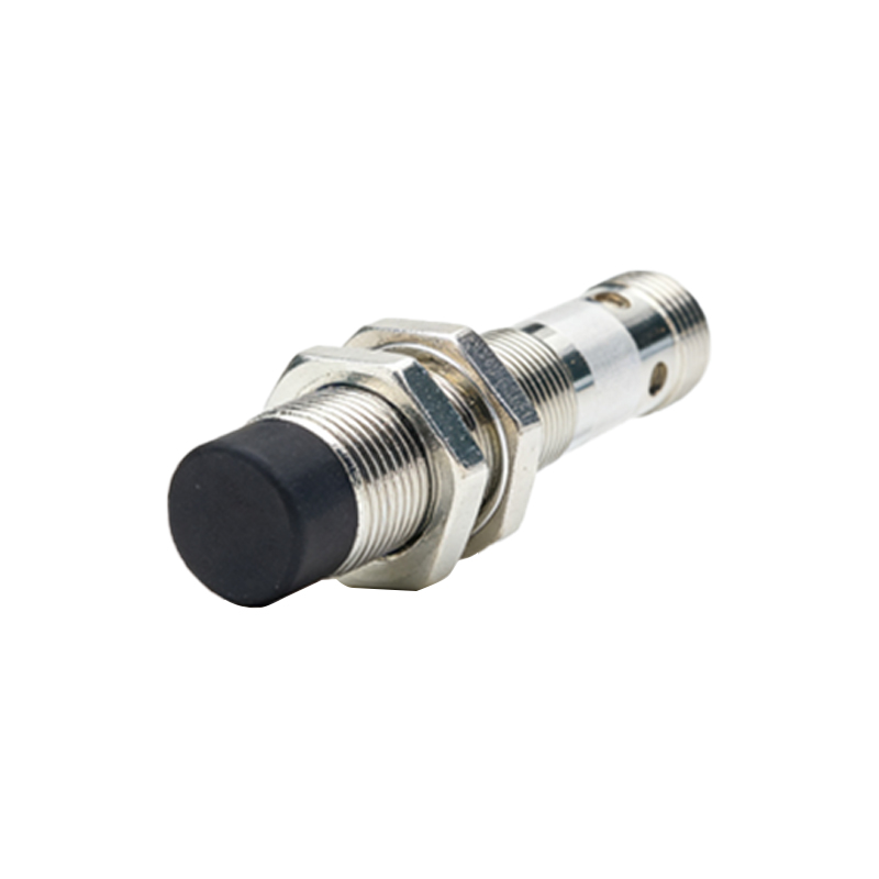
Proximity sensor coils are critical components in industrial automation, enabling non-contact detection of metallic objects through electromagnetic induction. The manufacturing process demands precision engineering and stringent quality control to ensure reliability, accuracy, and longevity in diverse operational environments. This article delves into the key stages of coil production, material selection, and testing protocols that define high-performance proximity sensors.
The journey begins with core material selection. Ferrite cores are commonly used due to their high magnetic permeability and low eddy current losses, which enhance sensitivity and response time. The core geometry—whether cylindrical, rectangular, or ring-shaped—is machined to tight tolerances, typically within ±0.1 mm, to maintain consistent magnetic field distribution. Surface polishing minimizes air gaps that could affect inductive coupling.
Wire winding is the heart of coil fabrication. High-purity copper magnet wire, insulated with polyurethane or polyimide, is wound onto the core using automated CNC winding machines. The number of turns, wire gauge, and winding pattern are precisely controlled based on sensor specifications. For instance, a typical inductive proximity sensor coil may have 100 to 500 turns of 0.05 mm to 0.2 mm diameter wire. Tension control during winding prevents wire deformation or insulation damage, which could lead to short circuits or reduced efficiency.
Encapsulation follows winding to protect the coil from environmental stressors. Epoxy resins or silicone-based compounds are injected into housings, providing mechanical stability, moisture resistance, and thermal insulation. The encapsulation material must have low shrinkage rates and high dielectric strength to withstand voltages up to 250 VAC. Curing is done in controlled ovens at temperatures around 80–120°C to avoid thermal stress on the windings.
Electrical testing validates performance parameters. Inductance (L) and quality factor (Q) are measured using LCR meters at operating frequencies, usually 10 kHz to 1 MHz. A deviation beyond ±5% from design values can indicate winding defects or core inconsistencies. High-potential tests apply voltages up to 1.5 kV to check for insulation breakdown. Additionally, temperature cycling tests from -25°C to 85°C ensure stability across industrial temperature ranges.
Advanced manufacturing incorporates laser trimming to fine-tune inductance by adjusting wire loops or core gaps. Automated optical inspection (AOI) systems scan for physical defects like wire misalignment or resin voids. For high-volume production, statistical process control (SPC) tracks parameters such as wire tension and cure time, reducing variability.
Material innovation continues to evolve. Amorphous or nanocrystalline cores are gaining traction for high-frequency sensors, offering lower core losses. Similarly, silver-plated copper wires can enhance conductivity in extreme conditions. However, these materials require specialized handling to avoid oxidation or brittleness during processing.
In summary, proximity sensor coil manufacturing blends traditional craftsmanship with modern automation. From core preparation to final testing, each step impacts the sensor’s detection range, hysteresis, and noise immunity. As Industry 4.0 drives demand for smarter sensors, manufacturers are adopting AI-driven predictive maintenance for equipment and integrating IoT-enabled monitoring in real-time production lines. By adhering to rigorous standards like IEC 60947-5-2, producers ensure coils meet global safety and performance benchmarks, enabling seamless integration into automotive, packaging, and robotics applications.