Proximity sensors are essential components in modern industrial automation, providing non-contact detection of metallic or non-metallic objects. Proper wiring is critical to ensure reliable operation, safety, and longevity of these sensors. This guide covers fundamental wiring principles, common configurations, and best practices for engineers and technicians.
Understanding the basic types of proximity sensors is the first step. Inductive sensors detect metallic objects, capacitive sensors handle non-metallic materials, and magnetic sensors respond to magnetic fields. Each type has specific wiring requirements, but most share common principles regarding power supply, output signals, and load connections.
Typically, proximity sensors have three or four wires. Three-wire sensors include power (brown or red), ground (blue or black), and output (black or white). Four-wire sensors often feature two outputs (e.g., normally open and normally closed) for greater flexibility. Always refer to the manufacturer’s datasheet for exact wire color codes, as standards can vary by region or brand.
Wiring configurations depend on the sensor’s output type: NPN (sinking) or PNP (sourcing). In NPN sensors, the output switches the negative side of the load to ground, common in Asian and European systems. PNP sensors switch the positive side, frequently used in North America. Incorrectly matching sensor output to the control system can lead to malfunctions or damage.
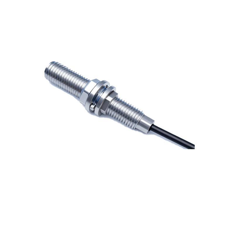
Step-by-step wiring process:
1. Disconnect all power sources to prevent electrical hazards.
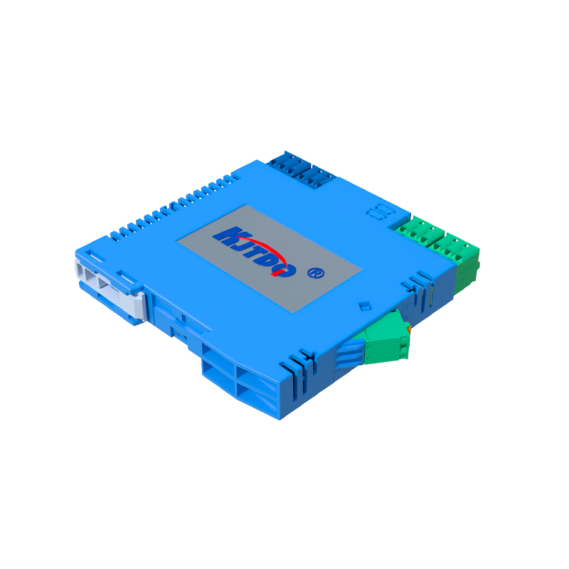
2. Identify sensor specifications: voltage range (commonly 10-30V DC), output type, and current rating.
3. Connect power wires: brown to positive DC, blue to negative DC. Ensure polarity is correct to avoid sensor failure.
4. Link the output wire to the load (e.g., PLC input, relay). For NPN sensors, connect the load’s positive side to power and the negative side to the sensor output. For PNP, connect the load’s negative side to ground and the positive side to the output.
5. Use shielded cables in environments with electromagnetic interference (EMI), grounding the shield at one end to reduce noise.
6. Secure connections with appropriate terminals, avoiding loose wires that may cause intermittent faults.
Common pitfalls include overloading the sensor output, exceeding voltage limits, or ignoring environmental factors like temperature and humidity. Always install sensors within their rated specifications and test operation before full deployment. For complex systems, consider using junction boxes or interface modules to simplify wiring and enhance maintenance accessibility.
In summary, meticulous wiring ensures proximity sensors perform accurately in demanding industrial settings. Adhering to standards, verifying connections, and consulting technical documentation are key practices for successful integration.