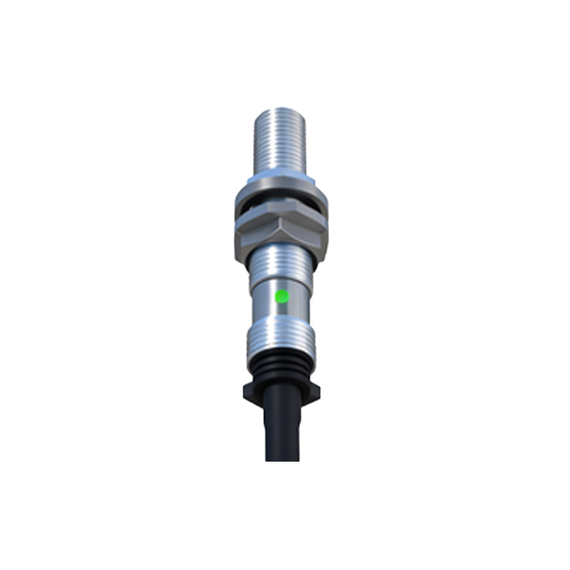
Proximity sensors are integral components in modern automation systems, enabling non-contact detection of objects within a defined range. The circuit design of these sensors directly impacts their reliability, accuracy, and application suitability. This article delves into the core principles and practical implementation of proximity sensor circuits, focusing on inductive, capacitive, and photoelectric types commonly used in industrial settings.
The fundamental operation of an inductive proximity sensor relies on electromagnetic induction. Its core circuit typically consists of an oscillator, a demodulator, a trigger, and an output stage. The oscillator generates a high-frequency electromagnetic field via a coil. When a metallic object enters this field, eddy currents are induced, causing a change in the oscillator's amplitude or frequency. The demodulator converts this change into a DC voltage signal. This signal is then compared against a predefined threshold by the trigger circuit (often a Schmitt trigger), which toggles the output stage—usually an NPN or PNP transistor or a solid-state relay—to provide a clean switching signal. Key design considerations include the selection of the oscillator frequency (typically between 100 kHz and 1 MHz), coil geometry for the desired sensing range, and stability against temperature variations and electrical noise. Shielding is crucial to minimize false triggers from adjacent metallic structures.
Capacitive proximity sensors, capable of detecting both metallic and non-metallic materials, operate on the principle of capacitance change. The circuit forms one plate of a capacitor, with the target object acting as the other plate. The core circuit includes an RC or LC oscillator whose frequency is influenced by the external capacitance. As an object approaches, the effective capacitance increases, altering the oscillation characteristics. This change is detected, often through a frequency-to-voltage converter, and processed by a threshold circuit. Design challenges involve sensitivity adjustment to compensate for different material dielectric constants and mitigating the effects of environmental humidity, which can alter stray capacitance. Proper grounding and guard ring techniques on the sensor face are essential to direct the electric field and improve stability.
Photoelectric proximity sensors use light beams for detection. The circuit design centers on an emitter (LED or laser diode) and a receiver (phototransistor or photodiode). In a modulated system, the emitter is driven by a pulsed current at a specific frequency (e.g., 10-50 kHz). The receiver circuit is tuned to this same frequency, incorporating a band-pass filter to amplify only the modulated signal. This design grants high immunity to ambient light. The receiver's output is fed into a comparator to generate a digital switch signal. Critical design parameters include the selection of emitter wavelength (infrared is common for its immunity to visible light), optical lens design for beam collimation or focusing, and compensation circuits for LED intensity degradation over time. For harsh environments, protection against dust and condensation must be factored into the housing and optical window design.
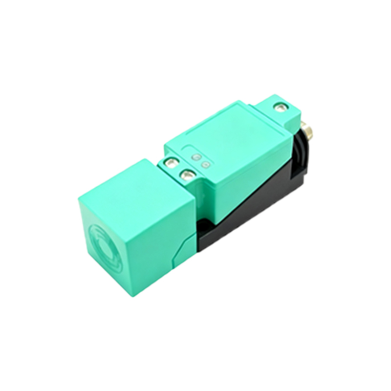
Power management and output interfacing are universal aspects. Most industrial proximity sensors operate on a wide DC supply range (10-30V DC). Voltage regulation and reverse polarity protection circuits are standard. The output stage must be robust, often featuring short-circuit and overload protection. For analog output variants, a precision current source (e.g., 4-20 mA) or voltage driver is implemented with low-temperature-drift components.
Signal integrity is paramount. Designers must incorporate filtering at both the power input and signal paths to suppress electromagnetic interference (EMI). Proper PCB layout—keeping high-frequency oscillator sections away from analog signal lines, using ground planes, and minimizing loop areas—is as important as the schematic itself. Compliance with international standards like IEC 60947-5-2 ensures reliability and safety in industrial environments.
In conclusion, effective proximity sensor circuit design requires a harmonious blend of theoretical understanding and practical engineering. It balances sensitivity, range, response time, and environmental robustness. By carefully selecting components, implementing noise-resistant architectures, and adhering to sound layout practices, engineers can develop sensors that deliver consistent performance in demanding applications, from factory assembly lines to consumer electronics.