Magnetic proximity sensors are indispensable components in modern industrial automation, machinery, and safety systems. Their ability to detect the presence or absence of a magnetic field without physical contact makes them reliable for position sensing, limit switching, and speed monitoring. However, like all electronic devices, they are susceptible to failure due to environmental factors, electrical issues, or mechanical damage. For electrical engineers and maintenance technicians, understanding systematic repair methodologies is crucial for minimizing downtime and ensuring operational continuity. This guide provides a comprehensive, step-by-step approach to diagnosing and repairing common faults in magnetic proximity sensors.
The initial phase of any repair process is accurate diagnosis. Begin by verifying the symptoms. Common failure indicators include a complete lack of output signal, intermittent operation, reduced sensing distance, or erratic behavior. Before disassembling the sensor, perform a preliminary check of the entire system. Ensure the target magnet is present, correctly aligned, and within the specified sensing range. Verify the power supply to the sensor using a multimeter; incorrect voltage (either too high or too low) is a frequent culprit. Check the wiring for loose connections, corrosion, or physical damage to the cables and connectors. A visual inspection of the sensor housing for cracks, dents, or signs of overheating can reveal mechanical or thermal stress.
If basic checks are inconclusive, proceed to electrical testing. For a standard three-wire DC sensor (brown/+, blue/-, black output), first confirm power between the brown (positive) and blue (negative) wires. With power applied, use the multimeter to measure the output voltage (black wire) relative to the negative (blue). Bring a known-good target magnet (often a simple neodymium magnet can suffice for testing) close to the sensing face. A functioning normally-open (NO) sensor should show a voltage shift (e.g., from near 0V to the supply voltage for a PNP type, or the reverse for an NPN type). No change indicates a potential internal fault. For two-wire AC/DC sensors, measure the voltage drop across the sensor or use a clamp meter to check current flow when activated.
Assuming external factors are ruled out, the fault likely resides within the sensor assembly. Important Safety Note: Always disconnect power before opening any sensor housing. The repair of the internal electronics requires a clean, static-free workspace and appropriate tools. Carefully open the sensor housing, which is often sealed with epoxy or O-rings. The internal components typically consist of a reed switch or a Hall-effect integrated circuit, signal conditioning electronics (amplifiers, Schmitt triggers), and output switching elements (transistors, relays).
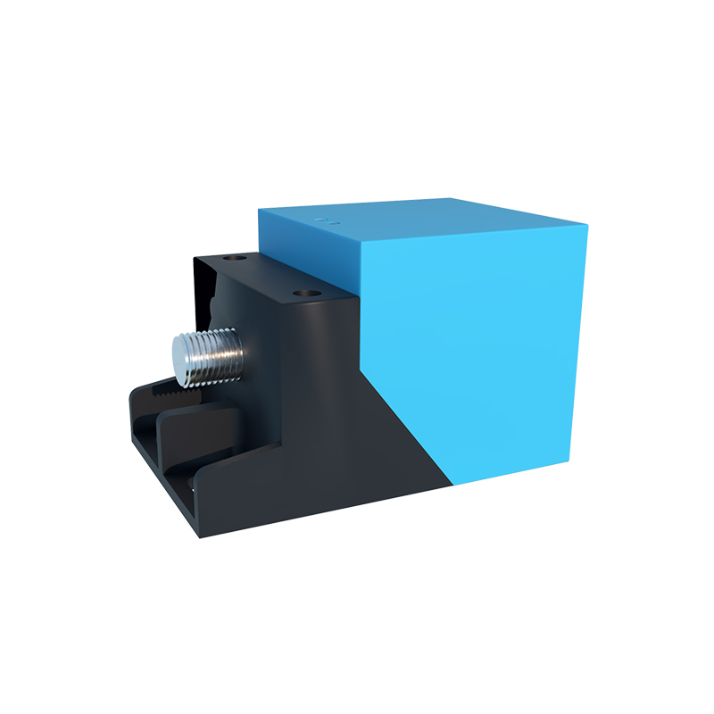
Examine the printed circuit board (PCB) for obvious defects: burnt components, cracked solder joints, broken traces, or signs of moisture ingress and corrosion. Use a magnifying glass for a detailed inspection. Pay special attention to the sensing element. For reed switch-based sensors, the glass capsule can crack or the reeds may fail to make contact. Gently test continuity with a multimeter while applying a magnetic field. For Hall-effect IC sensors, visual inspection is less revealing, and functional testing is key. Probe the IC pins according to its datasheet (if identifiable) to check for proper supply voltage and output response to a magnet.
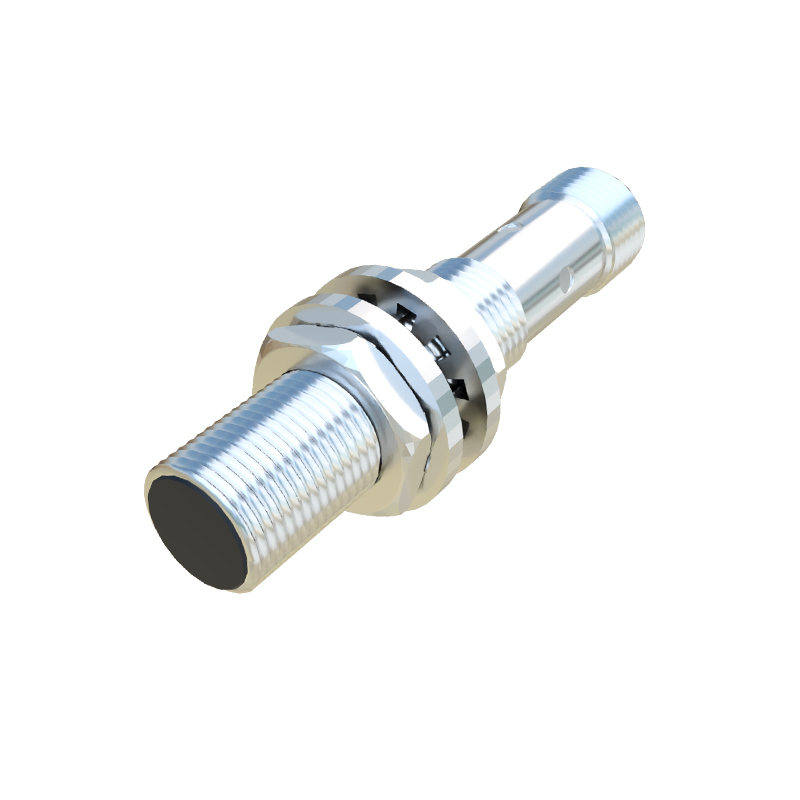
Component-level repair is often challenging due to miniaturization and potting compounds. However, some issues are repairable. Reflow any cracked or cold solder joints with a fine-tip soldering iron. Replace visibly damaged passive components like resistors or capacitors. If the sensing element (reed switch or Hall IC) is faulty, replacement is usually necessary. Desoldering a surface-mount Hall IC requires skill and proper equipment. For reed switches, sourcing an exact replacement with the same sensitivity and ratings is critical. If the output transistor is blown, identify its part number and replace it with an equivalent spec component. In many industrial sensors, the entire sensing head or internal module is available as a spare part, which can be a more time-efficient swap than microscopic component repair.
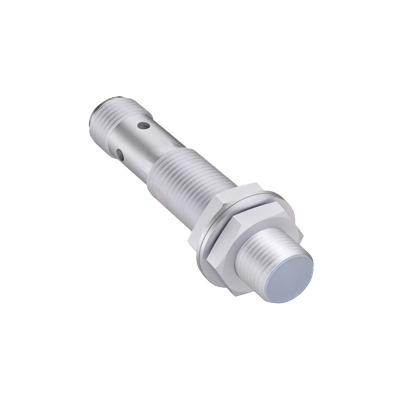
After any internal work, reassemble the sensor meticulously, ensuring all seals and gaskets are correctly positioned to restore the IP (Ingress Protection) rating. Before reinstalling it in the machine, perform a bench test. Reconnect power and verify the output signal with a multimeter or an oscilloscope while moving a target magnet through its sensing range. Confirm the switching characteristics (hysteresis) and the sensing distance meet the original specifications. It is also prudent to test the sensor under load, if possible, to ensure the output can drive the connected device (e.g., a PLC input, relay coil).
Finally, reinstall the sensor in its operational location. Ensure proper mounting, alignment with the target, and secure electrical connections. Conduct a final operational test within the full system cycle. Document the fault symptoms, diagnostic steps,