Proximity sensors are critical components in industrial automation, robotics, and safety systems, detecting the presence or absence of objects without physical contact. Proper calibration ensures accurate, reliable operation, minimizing false triggers and system downtime. This guide outlines the calibration process for inductive, capacitive, and ultrasonic proximity sensors, adhering to industry best practices.
First, understand the sensor type and specifications. Inductive sensors detect metallic objects, capacitive sensors sense both metallic and non-metallic materials, and ultrasonic sensors use sound waves for detection. Refer to the manufacturer’s datasheet for key parameters: sensing range, hysteresis, response time, and output type (e.g., NPN/PNP, analog, or digital). Ensure the sensor is correctly installed, with no obstructions in the sensing path, and that electrical connections comply with voltage and current ratings.
Begin calibration by powering the sensor and observing its default state. Use a target object matching the sensor’s design specifications—for inductive sensors, a standard metal target of defined size and material; for capacitive sensors, a material with appropriate dielectric constant; for ultrasonic sensors, a solid object at a known distance. Place the target at the minimum specified sensing distance. Adjust the sensor’s sensitivity or threshold setting, typically via a potentiometer, screw, or software interface. For analog sensors, monitor the output signal (e.g., 4-20 mA or 0-10 V) using a multimeter or oscilloscope. Gradually move the target toward the maximum sensing distance, verifying the output changes linearly without dropout.
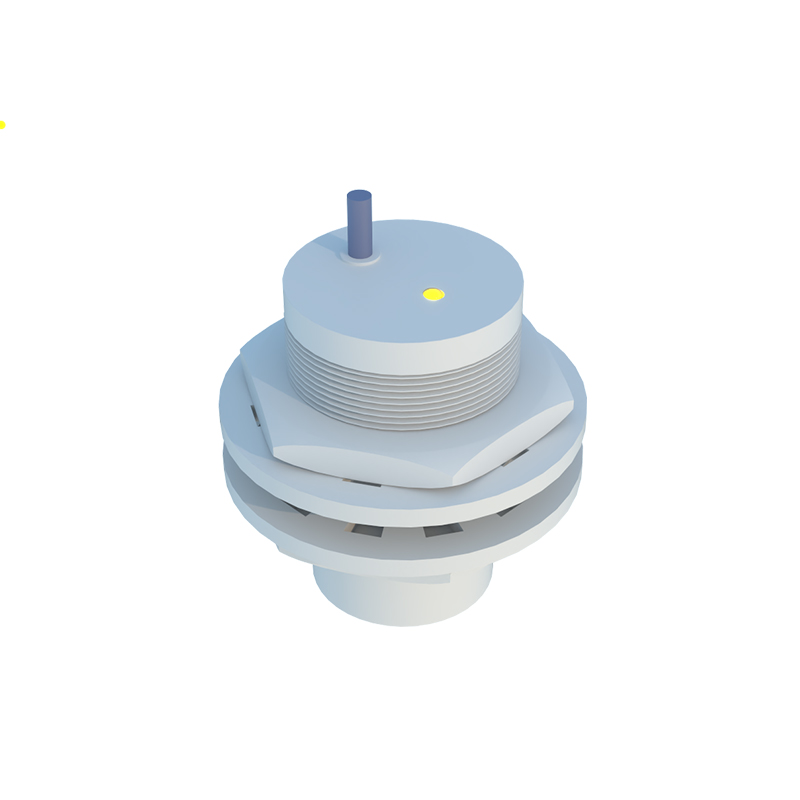
For digital sensors, calibration involves setting the switch point. Move the target to the desired activation distance, then adjust the sensitivity until the output toggles (e.g., from OFF to ON). Repeat this process multiple times to account for hysteresis—the difference between the switch-on and switch-off points. Hysteresis prevents chatter in dynamic environments; ensure it aligns with application needs. Record the calibrated values for future reference.
Environmental factors can affect calibration. Temperature fluctuations, humidity, electrical noise, or nearby machinery may interfere with sensor performance. Shield sensors from EMI using proper grounding and cabling. For capacitive sensors, avoid contamination from dust or liquids, which alter dielectric properties. Ultrasonic sensors may require compensation for air temperature changes affecting sound speed. Perform calibration under actual operating conditions when possible.
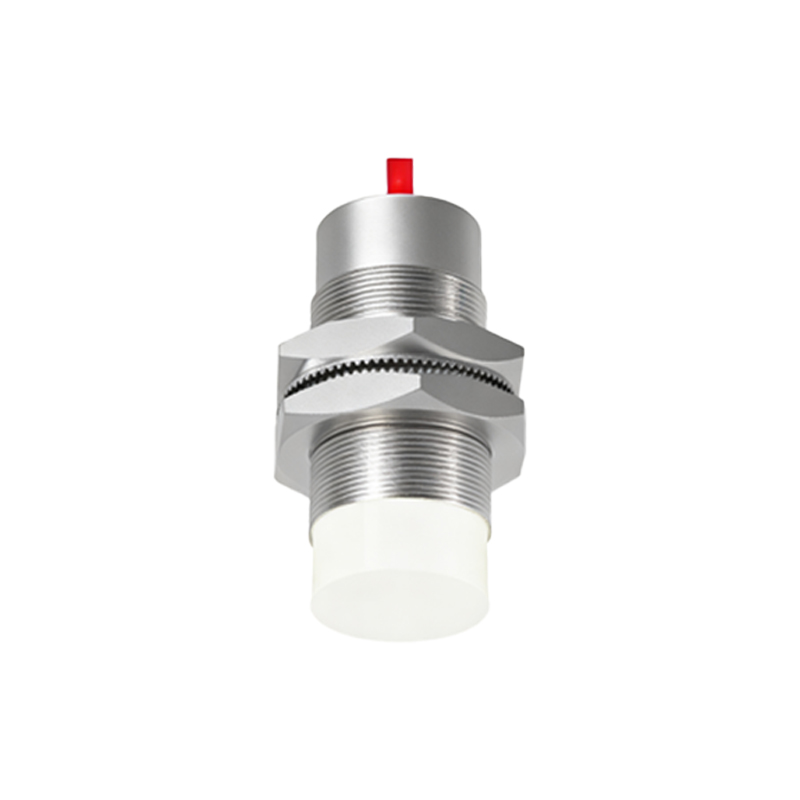
Validate calibration through testing. Cycle the target through the full sensing range at least 10-15 times, checking for consistent output. Use statistical tools to measure repeatability and accuracy. If deviations exceed tolerances, re-calibrate or consider sensor replacement. Document the calibration date, settings, and test results for maintenance records.
Advanced calibration techniques include using programmable logic controllers (PLCs) or sensor-specific software for automated tuning. Some smart sensors feature self-calibration via teach-in functions, where the sensor learns target positions at the push of a button. Regularly schedule recalibration based on operational hours or environmental shifts—typically every 6-12 months in harsh settings.
In summary, precise calibration enhances sensor longevity and system efficiency. Always follow manufacturer guidelines, account for application-specific variables, and maintain thorough documentation. By mastering these steps, engineers can ensure proximity sensors deliver optimal performance in diverse industrial scenarios.