Proximity sensors are fundamental components in modern industrial automation, robotics, and safety systems. Their ability to detect the presence or absence of an object without physical contact makes them indispensable. However, effective implementation hinges on precise measurement and configuration. This guide details the methodologies for measuring with proximity sensors, covering key parameters, setup procedures, and troubleshooting tips, tailored for electrical engineers and industry professionals.
Understanding the Core Measurement Principle
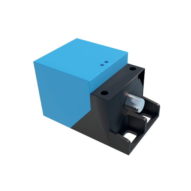
At its heart, a proximity sensor measurement is about converting a physical distance or presence into a reliable electrical signal. The primary output is typically a discrete ON/OFF signal (for inductive, capacitive, and ultrasonic types) or an analog signal proportional to distance (common in analog inductive or ultrasonic sensors). The critical measurement is the sensing distance, defined as the distance from the sensor's face to the standard target where the output switches state. This nominal sensing distance (Sn) is specified by the manufacturer under ideal conditions. Real-world measurement must account for factors like target material, size, temperature, and supply voltage variations, which can affect the actual operating point.
Key Parameters to Measure and Verify
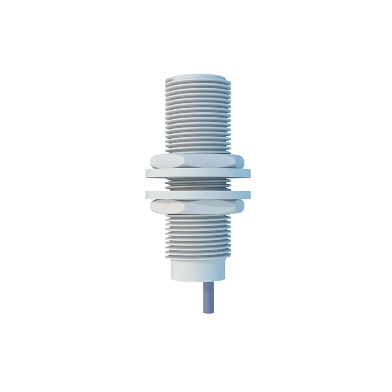
1. Actual Sensing Distance (Sa): This is the practical measurement. Using a calibrated target (e.g., a 1mm thick square of mild steel for inductive sensors), slowly move the target toward the sensor face. The point at which the output LED indicates activation and the switching signal is reliably sent to the controller is the actual sensing point. Measure this distance. It should fall within the manufacturer's tolerance range (usually 0-10% of Sn). Repeat this process moving the target away to measure the release point; the difference is the hysteresis, which prevents output chatter.
2. Switching Frequency: This measures how quickly the sensor can respond. It is defined as the maximum number of switching cycles per second. To measure, use a rotating disk with standard targets attached. Gradually increase the rotational speed until the sensor fails to detect every target consistently. The frequency at which it operates reliably is the maximum usable switching frequency, which must be higher than the application's required cycle rate.
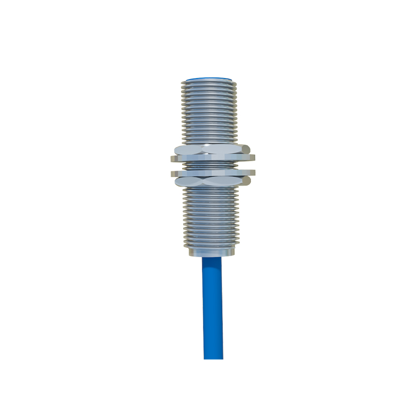
3. Output Signal Integrity: For digital sensors, measure the voltage level of the ON and OFF states using a multimeter or oscilloscope under load. Ensure the "ON" voltage is sufficiently high for the PLC input module (e.g., >10V for a 24V DC sensor) and the "OFF" voltage is low enough (e.g.,<2V). For analog sensors, verify the output curve (e.g., 4-20mA or 0-10V) across the entire sensing range. Check for linearity and ensure there is no signal noise or instability that could affect control loop performance.
4. Repeat Accuracy: This is crucial for precision applications. Fix the sensor and target. Repeatedly bring the target to the same measured position and record the variance in the output switch point. High-quality sensors exhibit minimal deviation. Environmental factors like temperature drift can affect this, so measurement under operating conditions is advised.
Step-by-Step Measurement Setup
Step 1: Power and Wiring: Connect the sensor to its specified power supply (e.g., 10-30V DC). Use shielded cables in electrically noisy environments and ensure proper grounding. Incorrect polarity can damage DC sensors.
Step 2: Target Selection: Use the correct standard target material and size. For inductive sensors, this is typically mild steel (Fe360). For capacitive sensors, the target material's dielectric constant affects sensing distance. Always refer to the datasheet correction factors for non-standard targets (e.g., aluminum, copper, stainless steel).
Step 3: Mounting: Ensure the sensor is securely mounted without vibration. For cylindrical sensors, maintain the recommended lateral clearance from metal mounting brackets to avoid flux field distortion, which shortens the sensing distance.
Step 4: Measurement Tools: Use precision measurement tools like digital calipers or a micrometer stage for distance measurement. An oscilloscope is invaluable for analyzing switching times, signal rise/fall times, and noise.
Step 5: Environmental Consideration: Measure under, or account for, the actual operating environment. Inductive sensors are immune to dust and dirt, but capacitive sensors can be triggered by moisture or chemical deposits. Ultrasonic sensors may be affected by air temperature and pressure changes.
Common Measurement Challenges and Solutions
Inconsistent Switching: Often caused by an unstable target (wobble), incorrect target material, or electrical noise. Verify target path stability, use the correct target, and employ ferrite cores on cables or RC snubber circuits to suppress noise.
Reduced Sensing Distance: Can result from voltage drop, improper mounting near metal, or a worn sensor face. Check supply