For engineers, technicians, and system integrators working with industrial automation, a fundamental yet critical question often arises: where exactly is the sensing area of a proximity sensor located? Understanding this is not merely academic; it is essential for correct installation, reliable operation, and optimal performance in any application. Unlike a simple mechanical switch, the active sensing zone of a non-contact proximity sensor is an invisible, three-dimensional field whose characteristics are defined by the sensor's technology, design, and specifications.
The core principle is that the sensing area is not a single point at the face of the sensor. It is a spatial region in front of the sensor where a target of specified size, material, and orientation can be detected. For inductive proximity sensors (used for detecting metals), the sensing field is generated by an oscillating coil. This electromagnetic field is strongest directly in front of the sensor and extends outward, diminishing in strength with distance. The standardized rated operating distance (Sn) specifies the theoretical point at which a standard target (usually a square of mild steel, 1mm thick, with sides equal to the sensor's diameter or 3xSn, whichever is smaller) will be detected. However, the effective sensing area extends slightly beyond and around this nominal point. The shape of this area is often approximated as a hemisphere or a short cylinder projecting from the sensing face.
For capacitive proximity sensors (used for detecting both conductive and non-conductive materials), the sensing field is an electrostatic field. This field tends to be broader and can be influenced by a wider range of materials and environmental factors. The sensing area is less defined and can sometimes extend to the sides of the sensor housing, making careful installation crucial to avoid false triggers from nearby objects or even the mounting bracket itself.
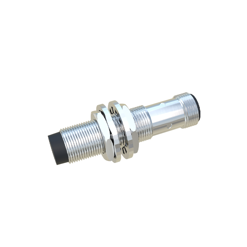
The location and extent of the sensing area are primarily determined by several key factors. First is the sensing technology: inductive, capacitive, ultrasonic, or photoelectric. Each creates a fundamentally different field shape. Second is the sensor design and housing shape. A cylindrical sensor has a more conical field, while a rectangular or block-style sensor may have a more rectangular field pattern. Shielded (flush-mountable) inductive sensors have a narrower, more focused frontal field, as the metal housing confines the magnetic flux. Unshielded (non-flush) sensors have a broader field that can extend to the sides, allowing for wider lateral detection but requiring more clearance from metallic surroundings.
Third, and most importantly, are the manufacturer's published specifications. The sensing range or operating distance is the primary datum. However, detailed datasheets often include diagrams showing the "sensing field contours" or "detection zones." These graphs illustrate how the effective sensing distance changes with the target's lateral offset. They visually answer the question of "where" by mapping the 3D space. For instance, a diagram might show that a target can be detected at 10mm when centered, but only at 8mm if it is 5mm off-center.
Practical implications are significant. Mounting Position: The sensor must be positioned so the target passes through the effective sensing area. For a cylinder passing by, the point of detection depends on whether it enters the field axially or radially. Multiple Sensor Installation: Sensors must be spaced far enough apart so their sensing fields do not interfere, causing mutual damping or false triggering. This is especially critical for inductive sensors. Target Characteristics: A larger target will be detected earlier (at a greater distance) as it enters the fringe of the sensing field. A smaller target must travel closer to the center to provide sufficient material to trigger the switch. The target material also affects the field penetration; for example, stainless steel has a lower detection range than mild steel for inductive sensors.
Installation Environment: Nearby metal (for inductive) or any material (for capacitive) can distort the sensing field, effectively shifting its location or size. This is called the "side-access" or "surrounding metal" effect. Always follow the manufacturer's guidelines for minimum clearance from surrounding metals as specified in the datasheet.
In conclusion, the sensing area of a proximity sensor is a dynamic, three-dimensional zone in front of the active face, not a flat plane. Its precise location and geometry are a function of the sensor's physics, mechanical design, and the target's properties. Relying solely on the nominal sensing range is insufficient for robust system design. Successful implementation demands a careful review of the technical datasheet, particularly the sensing field diagrams and installation notes. By understanding where the sensor "sees," engineers can ensure precise detection, enhance system reliability, and avoid costly installation errors, thereby maximizing the value of automation systems.