Infrared (IR) proximity sensors are integral components in modern automation, robotics, and safety systems. These sensors operate by emitting infrared light and measuring the reflection from nearby objects, enabling non-contact detection of presence, distance, or motion. As an electrical engineer, understanding how to effectively monitor and maintain these sensors is crucial for ensuring system reliability and performance.
The fundamental principle behind IR proximity sensors involves an IR LED that emits light and a photodiode or phototransistor that detects reflected signals. When an object enters the sensor's range, the reflected IR light intensity changes, which the detector converts into an electrical signal. This signal is then processed—often through amplification, filtering, and analog-to-digital conversion—to determine proximity. Common output types include digital (on/off) for simple detection and analog or PWM for distance measurement.
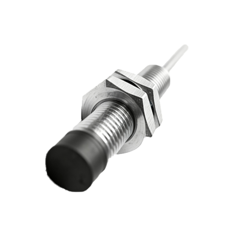
Monitoring these sensors begins with verifying their operational parameters. Key electrical characteristics to check include the forward voltage and current of the IR emitter, typically ranging from 1.2V to 1.6V and 20mA to 50mA, respectively. The detector circuit's output should be tested under known conditions: first with no object present (ambient reading), then with a standard reflective target at a specified distance. Oscilloscopes are invaluable here, allowing engineers to observe the modulated IR signal waveform, ensuring it is free from distortion or noise interference.
Environmental factors significantly impact IR sensor performance. Ambient infrared sources, such as sunlight or incandescent lighting, can saturate the detector, causing false triggers or reduced sensitivity. To mitigate this, many sensors use modulated IR signals—pulsing the emitter at a specific frequency (e.g., 38 kHz)—and tuning the receiver to that frequency. Engineers should confirm that this modulation/demodulation circuit is functioning correctly. Additionally, dust, fog, or colored/matte surfaces can attenuate IR reflection, necessitating periodic lens cleaning and sensitivity calibration.
In industrial settings, integrating IR proximity sensors with PLCs or microcontrollers is standard practice. Monitoring via software involves reading the sensor's output and comparing it against thresholds. For analog sensors, establish a baseline voltage for "no object" and a minimum voltage for "object detected." Implement software filtering, such as moving averages or debounce algorithms, to smooth out transient noise. For digital sensors, verify the logic levels: ensure the output switches cleanly between high and low states without floating values.
Diagnostic routines should be part of any system design. A simple heartbeat or status bit can indicate sensor health. More advanced diagnostics might involve a self-test mode where the sensor briefly activates and checks for a minimum reflection from a built-in reference surface. Regularly log sensor data—such as detection counts, output values, and error flags—to identify degradation trends, like decreasing sensitivity over time due to LED aging or lens contamination.
Calibration is essential for precision applications. Use calibrated distance targets to adjust potentiometers or digital registers controlling emitter current or detector gain. For sensors with temperature compensation, verify performance across the operating temperature range, as IR emission and detection efficiency can vary with temperature. Always refer to the manufacturer's datasheet for specific calibration procedures and environmental ratings.
Common failure modes include IR LED degradation, where output intensity diminishes after prolonged use, and detector damage from electrical surges or excessive light exposure. Circuit protection, such as current-limiting resistors for the emitter and transient voltage suppressors on signal lines, can extend sensor lifespan. When troubleshooting, use an IR viewer or a smartphone camera (which often detects IR) to visually confirm the emitter is active, and check for obstructions or misalignment.
In summary, proactive monitoring of infrared proximity sensors combines electrical testing, environmental management, software oversight, and preventive maintenance. By adhering to these practices, engineers can ensure accurate, reliable operation, minimizing downtime and enhancing the safety and efficiency of automated systems. As IR technology evolves with advancements like time-of-flight (ToF) sensors and integrated digital interfaces, the core principles of diligent monitoring remain a cornerstone of effective engineering.