As a seasoned electrical engineer specializing in industrial machinery maintenance, I often encounter issues with proximity switch sensors on band saws. These sensors are critical for ensuring precise cutting operations, safety interlocks, and automated material handling. Over time, factors like mechanical wear, environmental contaminants, or electrical surges can lead to sensor failure, necessitating replacement. This guide provides a detailed, industry-standard procedure for replacing proximity switch sensors on band saw machines, adhering to safety protocols and best practices.
Before initiating any work, ensure the band saw is completely powered off and locked out/tagged out (LOTO) to prevent accidental startup. Verify zero energy state using a multimeter. Gather necessary tools: appropriate screwdrivers, wrenches, a new proximity sensor matching the original specifications (e.g., NPN/PNP type, sensing distance, voltage rating), wiring diagrams, and personal protective equipment (PPE).
First, locate the faulty proximity sensor. Common placements include near the blade drive mechanism, feed systems, or safety gates. Inspect for visible damage, loose connections, or accumulation of metal chips and coolant. Document the existing wiring configuration by taking photos or sketching connections—this minimizes errors during reinstallation. Disconnect the electrical connector carefully; note that some sensors have quick-disconnect plugs while others may be hardwired into junction boxes.
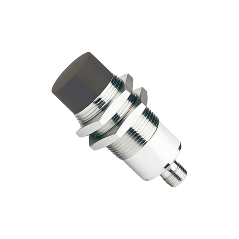
If hardwired, label each wire according to the diagram before disconnecting. Use a wrench to unscrew the sensor from its mounting bracket. Clean the mounting area thoroughly to ensure proper alignment and sensing accuracy for the new unit. Install the replacement sensor, tightening it securely but avoiding over-torquing, which could damage the housing. Reconnect the wires or plug precisely as per the original setup, ensuring correct polarity for DC sensors. Improper wiring can cause malfunction or damage to the control system.
After installation, perform a functional test without fully powering the machine. Temporarily remove the LOTO and energize the control circuit only. Use a metallic object to trigger the sensor, observing the indicator LED (if present) and monitoring the control panel for correct signal response. Verify that the sensor activates within its specified range. Once confirmed, de-energize and reapply LOTO before proceeding to mechanical checks.
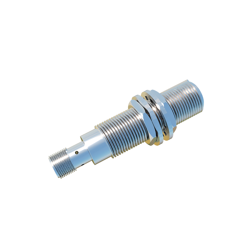
Next, inspect the alignment between the sensor and its target (e.g., a metal flag or gear tooth). Misalignment is a common cause of premature failure. Adjust the mounting position if needed, ensuring consistent detection without physical contact. Secure all brackets and conduits to prevent vibration-induced loosening.
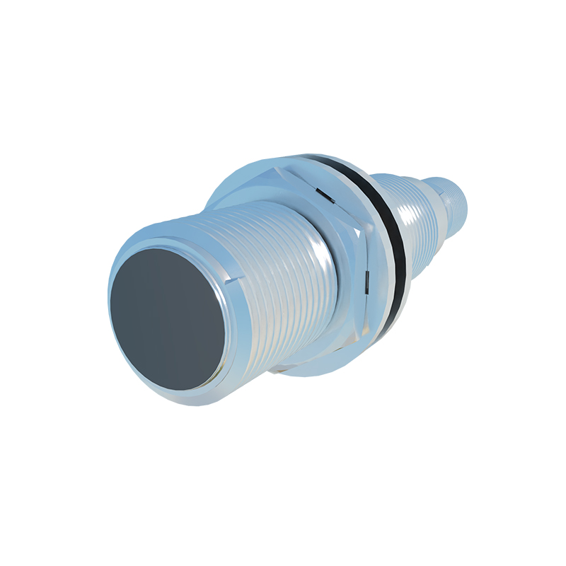
Finally, restore power and conduct a full operational test. Run the band saw through its typical cycles, checking for accurate cutting initiation, emergency stops, and automated sequences. Monitor for abnormal noises or delays in sensor response. Record the replacement in the maintenance log, including sensor model, date, and test results.
Regular maintenance, such as periodic cleaning and calibration, can extend sensor lifespan. Always source high-quality sensors from reputable manufacturers to ensure compatibility and reliability. In summary, replacing a proximity switch sensor requires meticulous attention to electrical safety, wiring accuracy, and mechanical alignment. By following these steps, downtime can be minimized, and optimal band saw performance maintained.