In the realm of industrial automation, proximity sensors serve as the critical "eyes" of machinery, providing non-contact detection of objects. The efficacy of these sensors, however, is wholly dependent on the performance and reliability of their trigger circuits. This article delves into the design principles, key components, and implementation strategies for robust proximity sensor trigger circuits, focusing on inductive and capacitive types prevalent in manufacturing environments.
The core function of a trigger circuit is to convert the subtle change in the sensor's oscillator state—caused by the presence of a metallic or non-metallic target—into a clean, definitive digital signal. This signal, typically a switch from a high to low logic state or vice-versa, is what the Programmable Logic Controller (PLC) or microcontroller interprets as an event. A well-designed circuit must achieve several objectives: high noise immunity to reject electromagnetic interference (EMI) common in industrial settings, appropriate switching speed for the application, and protection against voltage transients and incorrect wiring.
A standard trigger circuit comprises several stages. Following the sensor head's internal oscillator and demodulator, the signal enters a comparator stage. This is the heart of the triggering mechanism. The comparator contrasts the sensor's analog output voltage against a precise reference voltage. When the target enters the sensing field, the output voltage shifts. Once it crosses the threshold set by the reference, the comparator's output snaps to its saturated state, creating a sharp digital edge. Hysteresis, often implemented via positive feedback, is crucial here. It creates two distinct thresholds: one for turning ON and a lower one for turning OFF. This hysteresis prevents output oscillation or "chatter" when the target is at the borderline of the sensing range, ensuring a single, clean transition.
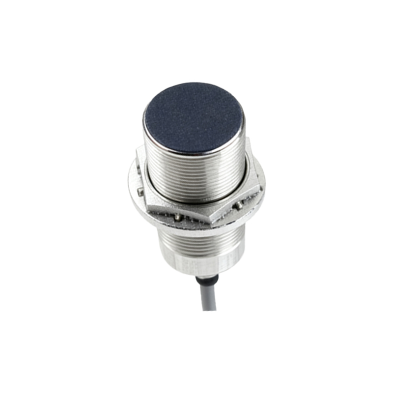
Following the comparator, a buffer or driver stage amplifies the current capability of the signal to reliably drive opto-isolators, relay coils, or direct PLC inputs. For interfacing with PLCs, an NPN (sinking) or PNP (sourcing) transistor output is standard. Protection components are non-negotiable. Flyback diodes across inductive loads (like relays), RC snubber networks, and Transient Voltage Suppression (TVS) diodes safeguard the sensitive semiconductor components from voltage spikes induced by long cable runs or switching inductive loads nearby.
For capacitive proximity sensors, which detect non-metallic materials, the circuit design must account for higher sensitivity to environmental factors like humidity or contamination. Shielding and proper grounding become even more critical to prevent false triggering. Some advanced designs incorporate programmable delay timers (on-delay, off-delay) or window comparators within the trigger circuitry itself, allowing for more complex logic, such as detecting an object of a specific size by its dwell time in the sensing field.
Implementation requires careful consideration of the power supply. A regulated, low-ripple DC supply is mandatory. In 24VDC systems, common in industry, ensuring the circuit operates correctly over the entire voltage range (often 10-30VDC) is key. PCB layout practices are equally important: keeping analog and digital grounds separated, using short traces for the comparator section, and providing adequate decoupling capacitors near each integrated circuit.
In conclusion, the trigger circuit is not merely an add-on but the defining component that translates a sensor's physical detection into actionable industrial data. A design prioritizing hysteresis, protection, and noise immunity will deliver the reliability demanded by continuous operation environments. As sensor technology evolves with IO-Link and other smart interfaces, the fundamental principles of creating a stable, robust trigger signal remain the bedrock of effective automation system integration.