In the realm of industrial automation and control systems, the inductive proximity switch stands as a fundamental and robust sensing solution. These non-contact sensors are engineered to detect the presence or absence of metallic objects without any physical contact, making them indispensable in harsh environments where reliability, speed, and durability are paramount. Their operation is elegantly simple yet highly effective, based on the principle of electromagnetic induction.
At the core of an inductive proximity sensor is an oscillator circuit that generates a high-frequency electromagnetic field emanating from the active face of the sensor. This field is typically generated by a coil wound around a ferrite core. When a metallic object, known as the target, enters this oscillating field, eddy currents are induced on the surface of the target. These eddy currents draw energy from the oscillator, causing a reduction in the amplitude of the oscillation. An integrated evaluation circuit within the sensor monitors this amplitude change. Once the amplitude drops below a predetermined threshold—indicating the target is within the specified sensing range—the sensor's output state switches. This output can be either a solid-state switch (PNP or NPN transistor) or a relay contact, providing a clear signal to a Programmable Logic Controller (PLC) or other control device.
The performance characteristics of inductive proximity switches are defined by several key parameters. The sensing distance, or nominal range (Sn), is a critical specification, typically ranging from a few millimeters to about 60 mm for standard cylindrical models. It's important to note that this rated distance is defined for a standard target of mild steel. Different metals affect the sensor's range due to their varying electrical conductivity and magnetic permeability. For instance, stainless steel may reduce the effective sensing distance, while copper or aluminum reduces it even further. This factor is accounted for by a reduction factor provided in datasheets. Another vital specification is the switching frequency, which denotes how many times per second the sensor can detect an object. High-speed models are essential for counting or high-throughput packaging applications. Hysteresis is the difference between the switch-on point (as the target approaches) and the switch-off point (as it moves away), which prevents output chatter when a target is at the exact sensing limit.
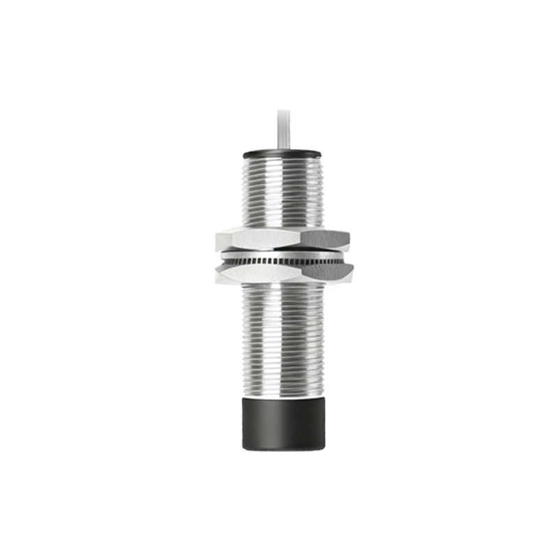
The advantages of using inductive proximity sensors are numerous. They are exceptionally rugged, with many models featuring housings made of nickel-plated brass, stainless steel, or high-grade plastics like PBT, offering high resistance to mechanical shock, vibration, and environmental contaminants like oil, coolants, and dust (often rated IP67, IP68, or IP69K). Their solid-state design ensures a long operational life with no moving parts to wear out. They are immune to ambient light and can operate in complete darkness, unlike optical sensors. Furthermore, they provide precise and repeatable detection, which is crucial for positioning and sequencing tasks.
Applications for inductive proximity switches are vast across manufacturing and process industries. Common uses include:
Position Detection: Verifying the presence of a metal part on a conveyor, the end position of a cylinder, or the open/closed status of a metal door or guard.
Counting: Tallying metal parts, bottles with metal caps, or cans on a production line.
Speed Monitoring: Used in conjunction with gear teeth or encoder wheels to measure rotational speed.
Machine Tooling: Tool breakage detection, spindle positioning, and pallet shuttle verification.
Material Handling: Level detection in metal bins or hoppers.
Selecting the right inductive proximity switch requires careful consideration of the application requirements. Key selection criteria include:
1. Sensing Distance: Choose a sensor with a nominal range slightly greater than the required mounting distance to account for installation tolerances and target variations.
2. Target Material and Size: Confirm the sensor's performance with the specific target metal. The target must also be at least as large as the sensor's active face for reliable detection.
3. Housing Style and Size: Cylindrical (threaded barrel) sensors (e.g., M8, M12, M18, M30) are most common. Also consider rectangular or ring-shaped formats for specific mounting needs.
4. Output Configuration: Decide between PNP (sourcing) or NPN (sinking) transistor outputs based on the input type of your controller. Also choose between Normally Open (NO) or Normally Closed (NC) logic.
5. Connection Type: Options include pre-wired cables, quick-disconnect connectors (e.g., M12), or terminal connections.
6. Environmental Ratings: Ensure the Ingress Protection (IP) rating and temperature range are suitable for the operating environment, which may involve washdowns, extreme temperatures, or chemical exposure.
7. Special Features