In the realm of industrial automation and control systems, proximity sensors are indispensable components for non-contact detection of objects. A critical, yet sometimes overlooked, electrical parameter of these sensors is their internal resistance. This resistance, often specified under specific conditions, plays a pivotal role in sensor performance, circuit design, and system reliability. Unlike a simple resistor, the resistance of a proximity sensor is not a static value but a dynamic characteristic influenced by its type, construction, and operating state.
Primarily, we must distinguish between the two dominant technologies: inductive and capacitive proximity sensors. For inductive sensors, designed to detect metallic objects, the key resistive component is the coil. The DC resistance of this coil is a fixed value, typically ranging from a few tens to a few hundred ohms, depending on the sensor's size and design. This coil resistance (Rcoil) is crucial as it directly impacts the sensor's current draw and thermal characteristics. When powered, the sensor's oscillator circuit becomes active, and the effective impedance is a complex combination of this DC resistance and the inductive reactance of the coil. The detection event itself—when a metal object enters the sensing field—causes eddy current losses in the target, which effectively increases the resistive damping in the oscillator circuit. This change in the circuit's effective resistance, not the DC coil resistance alone, is what the sensor's electronics interpret to trigger a switching output.
Capacitive sensors, used for detecting both metallic and non-metallic materials, operate on a different principle. Their sensing element forms a capacitor. The resistance here is less about a physical coil and more about the leakage resistance and the impedance of the oscillator circuit. The presence of a target material alters the dielectric constant, changing the capacitive reactance. The sensing electronics monitor the current flow in this RC network, where changes in effective resistance due to the altered capacitance are key to detection.
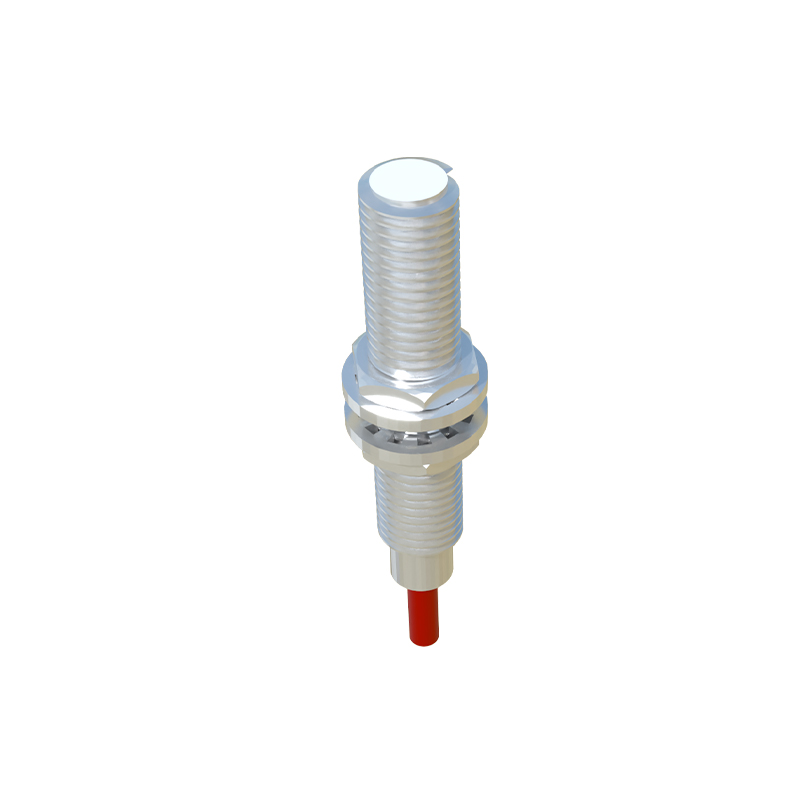
From a practical wiring and interfacing perspective, the output stage resistance is paramount. For a 3-wire DC sensor, the solid-state switch (typically a transistor) has an ON-state resistance (Rds(on) for MOSFETs or saturation resistance for BJTs). This value, usually very low (in the milliohm to single-digit ohm range), determines the voltage drop across the sensor when the load is energized. A high ON-resistance can lead to excessive voltage drop, potentially causing the load (like a PLC input or relay coil) to malfunction due to insufficient voltage. Conversely, the OFF-state resistance is extremely high (megaohms), ensuring minimal leakage current.
For 2-wire AC/DC sensors, the situation involves the voltage drop across the sensor in the conducting state. This is often specified as a maximum "voltage drop" at rated current, which inherently defines an effective resistance (R = Vdrop / I). This resistance must be accounted for in the design to ensure the load receives adequate voltage.
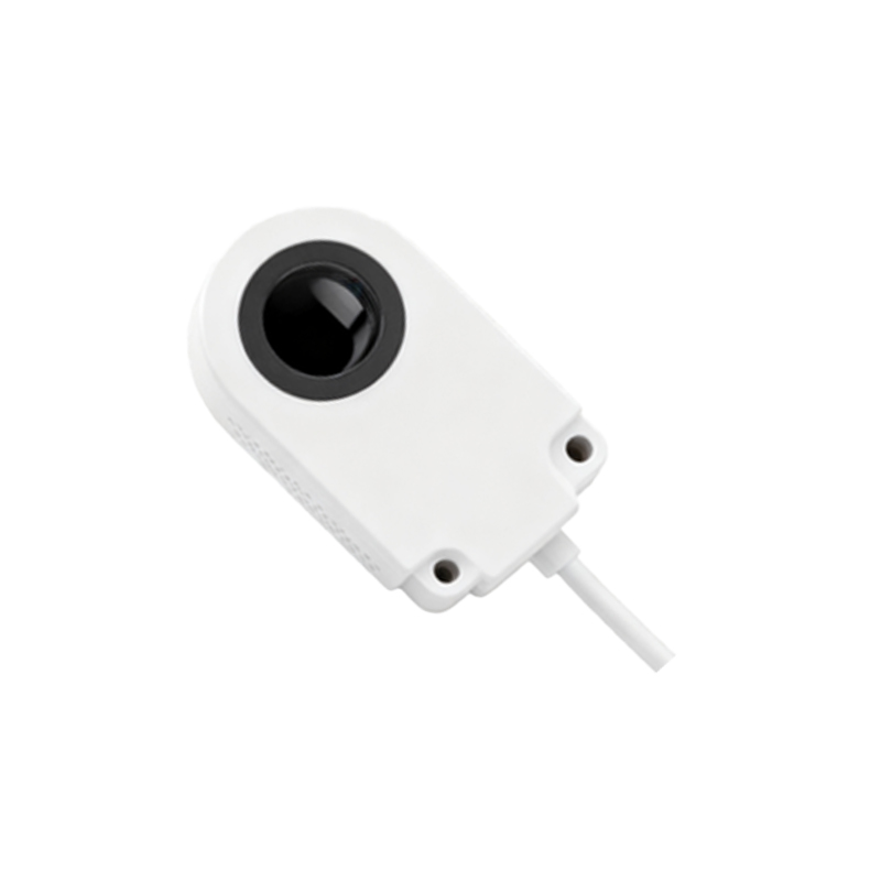
Understanding these resistance values is critical for troubleshooting. Measuring the DC coil resistance of an inductive sensor with a multimeter can verify winding integrity; an open circuit (infinite resistance) indicates a broken coil, while a very low resistance might suggest a short. However, a correct DC resistance reading does not guarantee the oscillator circuit is functional. When diagnosing output failures, measuring the voltage drop across the output terminals under load can reveal an abnormally high ON-resistance, pointing to a failing output transistor.
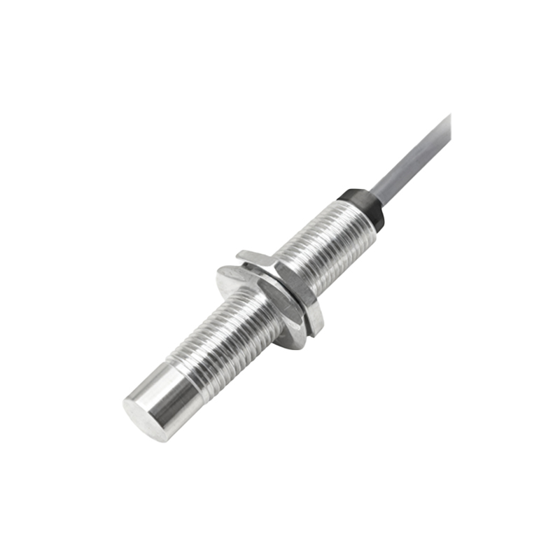
Environmental factors also significantly impact sensor resistance characteristics. High ambient temperatures can increase the copper winding resistance of inductive coils (due to copper's positive temperature coefficient). While modern sensors are designed to compensate for this within their operating range, extreme conditions can shift parameters beyond compensation limits, affecting sensing distance and stability. Contamination, such as conductive dust or metallic swarf bridging sensor terminals, can create parallel leakage paths, effectively lowering the insulation resistance and causing false triggering or sensor damage.
In summary, the concept of "resistance" in proximity sensors is multifaceted. It encompasses the fixed DC resistance of internal coils, the dynamic effective resistance of oscillating circuits during sensing, and the critical ON/OFF resistance of the output switching element. Engineers and technicians must consult the manufacturer's datasheet for specific values—such as coil resistance, maximum voltage drop, or minimum insulation resistance—to ensure proper sensor selection, circuit design, and maintenance. Ignoring these parameters can lead to system instability, reduced sensing performance, and premature sensor failure, ultimately impacting the productivity and safety of automated industrial processes.