Proximity sensors are indispensable components in modern industrial automation, providing non-contact detection of metallic or non-metallic objects. Correct wiring is paramount for ensuring reliable operation, safety, and longevity of both the sensor and the connected control system. This guide details the standard wiring methods for the most common types of proximity switches: DC 3-wire, DC 2-wire, and AC 2-wire configurations.
Understanding the Core Types
Before delving into wiring, it's crucial to identify the sensor type. Inductive proximity sensors detect metallic objects, while capacitive sensors can detect both metallic and non-metallic materials. Furthermore, sensors are classified by their output configuration: NPN (sinking) or PNP (sourcing) for DC models, and normally open (NO) or normally closed (NC) contacts for all types. The wiring diagram, typically found on the sensor body or datasheet, is the primary reference.
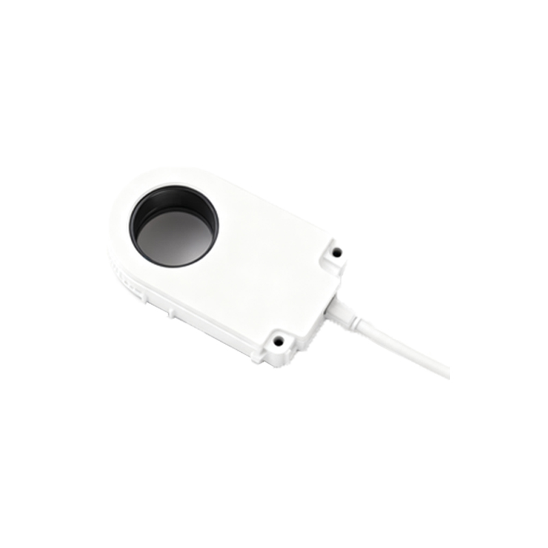
DC 3-Wire Proximity Sensor Wiring
This is the most prevalent configuration in PLC-based systems due to its stable performance and separate supply and signal paths. The three wires are usually color-coded: brown for positive supply (+V), blue for common negative (0V), and black for the output signal.
PNP (Sourcing) Wiring: The brown wire connects to the positive DC supply voltage (e.g., +24VDC). The blue wire connects to the power supply negative (0V) and also to the common terminal of the PLC input module. The black output wire connects to the specific PLC input channel. When the sensor detects a target, it sources current, switching the black wire to supply voltage, thereby sending a +24V signal to the PLC input.
NPN (Sinking) Wiring: The brown and blue wires connect to +V and 0V respectively, as above. The key difference is that the blue wire also connects to the PLC input common, which must be positive (+24V). The black output wire connects to the PLC input. When activated, an NPN sensor sinks current, connecting the black wire to 0V, pulling the PLC input low to complete the circuit.
Critical Consideration: Mismatching PNP and NPN sensors with the opposite PLC input type will result in non-operation. Always verify the PLC input module is configured for sinking or sourcing.
DC 2-Wire Proximity Sensor Wiring
These sensors simplify installation by combining supply and load current in two wires, similar to a mechanical switch. They are connected in series with the load (e.g., a PLC input) and the power supply.
Wiring Method: One wire connects to the positive DC supply. The other wire connects to one terminal of the load. The second terminal of the load then connects to the supply negative. There is no polarity sensitivity; they can be wired in either direction.
Important Notes: 2-wire DC sensors have a residual voltage drop (leakage current) when "off" and a voltage drop when "on." This residual current must be below the PLC input's "OFF" threshold to prevent false triggering. Conversely, the "ON" state voltage must be high enough to be reliably detected. Consult both sensor and PLC specifications to ensure compatibility.
AC 2-Wire Proximity Sensor Wiring
These are directly compatible with standard AC line voltage (e.g., 120VAC, 240VAC). They are also connected in series with the load.
Wiring Method: One wire connects to the live (hot) AC terminal. The other wire connects to one terminal of the load (e.g., a relay coil, contactor, or AC PLC input). The second load terminal connects to the neutral line. Proper insulation and adherence to local electrical codes for AC power wiring are mandatory.
Key Characteristics: AC sensors typically have higher leakage currents than DC models. They may also generate more electrical noise. Using a shielded cable and proper grounding is often recommended. Ensure the load's minimum operating current is less than the sensor's rated current, and the maximum current is not exceeded.
Universal Best Practices for Wiring
1. Power Disconnect: Always lock out and tag out (LOTO) all power sources before beginning wiring work.
2. Use of Datasheet: Never assume wire colors; always use the manufacturer's datasheet for the specific model.
3. Cable Selection: Use shielded, twisted-pair cables for long runs or electrically noisy environments. Connect the shield to ground at the control panel end only.
4. Surge Protection: Install surge suppressors or varistors on the sensor lines if they are exposed to inductive loads like solenoids or motors.
5.