In industrial automation and control systems, proximity sensors are indispensable components for non-contact detection of metallic or, in some cases, non-metallic objects. Their reliability is paramount for ensuring seamless production flow, machine safety, and process accuracy. However, like any electrical component, proximity sensors and their associated circuits are susceptible to faults. This article delves into the common types of proximity sensor circuit failures, their root causes, systematic diagnostic procedures, and effective corrective measures, providing a comprehensive guide for electrical engineers and maintenance technicians.
A proximity sensor circuit typically consists of the sensor itself (inductive, capacitive, or photoelectric), a power supply, and a load (often a PLC input module, relay, or indicator). Faults can manifest in any part of this chain. The most frequent symptoms include intermittent operation, complete failure to detect objects, constant "ON" state regardless of object presence, or erratic switching behavior. Understanding the underlying cause is the first step toward a solution.
One prevalent category of faults is Power Supply Issues. An unstable, undervoltage, or overvoltage DC supply can cause a sensor to behave unpredictably or not function at all. For AC-powered sensors, voltage fluctuations or frequency mismatches can be equally detrimental. Always verify the supply voltage at the sensor's terminals under load conditions using a reliable multimeter. Ensure the power source matches the sensor's specifications precisely. Ripple or noise on the DC line, often from nearby variable frequency drives (VFDs) or switching power supplies, can also interfere with sensor operation. Implementing proper filtering, using shielded cables, and ensuring a solid, clean earth ground are critical preventive steps.
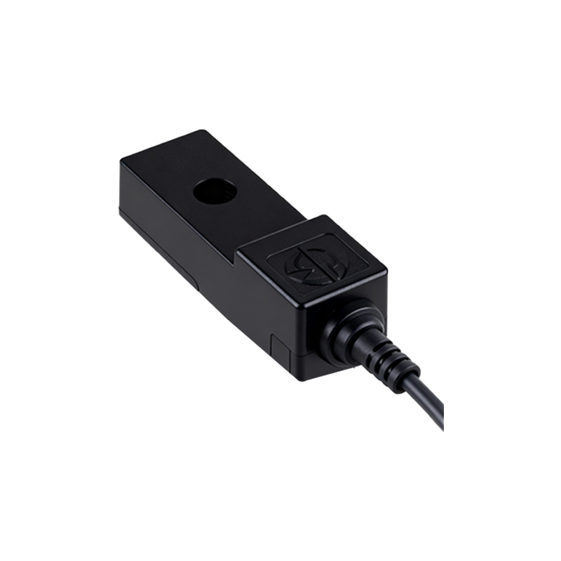
Wiring and Connection Faults constitute a significant portion of field problems. These include loose terminal screws, corroded contacts, damaged cable insulation, and broken wires within the cable conduit, often due to mechanical stress or vibration. For 2-wire AC/DC sensors, incorrect polarity or mixing of wiring with a 3-wire sensor type will prevent operation. In 3-wire configurations (PNP or NPN), a common mistake is confusing the load connection between the sensor's output wire and the supply common. A thorough visual inspection of the wiring, followed by continuity and resistance checks with the circuit de-energized, is essential. Pay close attention to cable glands and entry points, which are common failure locations.
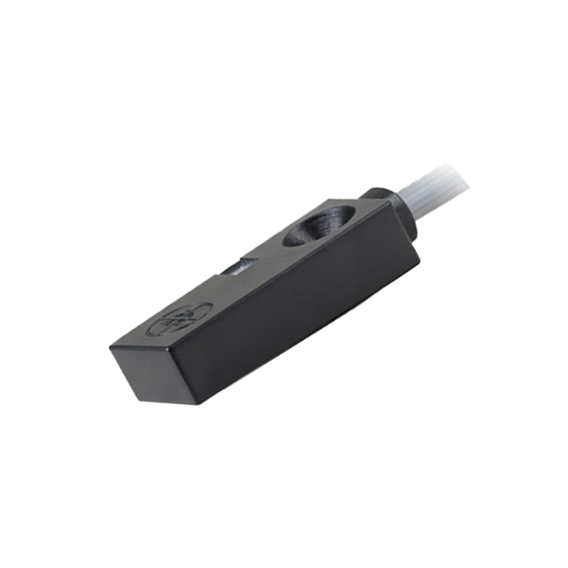
Sensor Misapplication and Environmental Factors often lead to premature failure or erratic performance. Inductive sensors have a defined sensing range and are designed for specific metals. Attempting to detect a non-ferrous metal like aluminum at the rated distance for steel can result in reduced range or failure. Capacitive sensors can be falsely triggered by humidity, dust buildup, or conductive contaminants on the face. Extreme temperatures beyond the sensor's rating can cause internal component drift or permanent damage. Chemical exposure can degrade housing materials and seals. Always consult the datasheet for environmental ratings (IP, NEMA), temperature range, and sensing distance derating factors. Ensuring the correct sensor type for the application and environment is a design-stage necessity that prevents countless field issues.
Electrical Noise and Interference (EMI/RFI) is a subtle yet disruptive fault source. High-frequency noise from arc welders, radio transmitters, or motor brushes can be induced into sensor cables, causing false triggering. Long, unshielded cable runs parallel to power cables act as perfect antennas. The solution lies in proper installation practices: use shielded, twisted-pair cables for sensor signals, ground the shield at only one end (typically the control panel end), physically separate signal cables from power lines by at least several inches, and employ ferrite cores on cables near noise sources.
Internal Sensor Failure, while less common than wiring issues, does occur. The oscillator circuit in an inductive sensor can fail. The output transistor in a solid-state sensor can short or open. Diagnosing this often involves a process of elimination. First, isolate the sensor from its wiring by disconnecting it. Using a multimeter, check the sensor's output behavior according to its data sheet. For a 3-wire PNP sensor, apply correct power. With no target present, the voltage between the output wire and common should be near 0V (OFF). When a valid target is brought within sensing distance, the voltage should rise to near the supply voltage (ON). The opposite is true for NPN sensors. If the sensor fails this basic test with confirmed good power and wiring, the sensor is likely faulty. Remember, some sensors have built-in LED indicators that provide valuable diagnostic clues.
A systematic approach to troubleshooting is key. Start with the simplest checks: verify power, inspect for physical damage, and confirm the target material and distance. Use diagnostic tools effectively: a multimeter for voltage and continuity, an oscilloscope to check for noise on the line, and for