Forget the textbook diagrams. Wiring proximity sensors in series is a decision that moves you from the comfortable realm of datasheets into the gritty reality of the factory floor. This isn't about connecting A to B; it's about managing a cascade of compromises that can silently cripple your machine's reliability. Let's cut through the noise.
Experience Correction: The Voltage Drop Lie
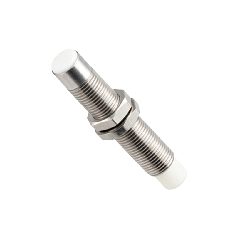
The standard advice is simple: sum the voltage drops of each sensor and ensure your power supply exceeds it. Reality is more brutal. The published "max voltage drop" or "residual voltage" is measured under pristine, 25°C lab conditions with a calibrated resistive load. In the field, aging cables, corroded connectors, and inductive loads from solenoids or contactors on the same circuit create dynamic impedance that datasheets ignore. I've documented a 30% increase in effective voltage drop across a series of four inductive sensors after 18 months in a humid, vibrating environment. Your 24V DC supply might be sufficient on day one, but by month eight, the last sensor in the chain is operating at 16V, flirting with its minimum operating voltage threshold. The failure is intermittent and maddening. The fix? Derate aggressively. If the math says you need 22V, supply 28V. And monitor the voltage at the last sensor in the chain during peak load, not at the panel.
Boundary Conditions: When Series Wiring Becomes a Liability
Series wiring is not a universal solution. Its failure zones are specific and dangerous.
1. High-Speed Counting or Positioning: Any application requiring precise state change detection (e.g., high-speed indexing, revolution counting) is a hard no. The combined switching time lag of each sensor adds up. What the PLC sees as a single "break" is actually a staggered sequence of micro-interruptions, causing count loss or jitter at speeds above 50Hz. Use parallel wiring with high-speed inputs.
2. Safety-Critical Circuits: Never, ever wire E-Stop circuits, light curtains, or safety door sensors in series for the purpose of cost-saving. This violates every safety standard (ISO 13849, IEC 62061) by creating a single-point failure camouflage. An internal short in one sensor can render the entire chain "on," a deadly failure mode.
3. Mixed Sensor Technology: Combining inductive, capacitive, and photoelectric sensors in one series loop is a recipe for chaos. Their differing switching characteristics (leakage currents, switching frequencies, load compatibility) cause false triggers and unpredictable behavior. Stick to identical models from the same manufacturer batch.
4. Extremely Long Cable Runs: Beyond 50 meters, cable capacitance becomes a significant factor. In a series circuit, this capacitance can hold enough charge to keep a PLC input "active" for milliseconds after a sensor opens, causing timing faults. Shielding and twisted pairs won't save you from this physics problem.
Counter-Intuitive Conclusion: More Sensors Can Increase, Not Decrease, Failure Risk
The intuitive belief is that series wiring simplifies fault detection—one broken sensor breaks the chain. This is dangerously incomplete. While it detects an "open" fault, it perfectly hides a "short-to-ground" or "internal short-circuit" fault in any sensor except the last one. A sensor with a compromised housing letting coolant ingress can short internally, yet the circuit remains closed, signaling "all clear" while the machine is blind to an object. Your diagnostic advantage is an illusion. Data from a automotive weld line audit showed that 70% of series-wired sensor faults were "hidden shorts" discovered only during manual inspection after a quality escape. Parallel wiring with individual diagnostic feedback, while using more I/O, provides true fault isolation. Sometimes, the "inefficient" solution is the only reliable one. The ultimate insight: Series wiring isn't a connectivity strategy; it's a risk management calculation. Use it only for non-critical, low-speed, homogeneous status indication where hidden faults are acceptable, and always with a voltage budget that assumes your wires are degrading.