Forget what you read in the catalog. After two decades on factory floors, from food processing to heavy machining, I've seen the gap between sensor theory and gritty reality. Here’s what matters when the rubber meets the road.
Experience Correction: The Illusion of Rated Sensing Distance
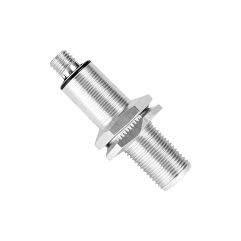
The stated sensing distance (Sn) is a laboratory fantasy. It's calibrated for a standard target: a grounded square of mild steel. In reality, your target is rarely perfect. A non-grounded plastic bottle, a moisture-laden wood pallet, or a thin aluminum foil—each behaves drastically differently. The effective sensing distance can drop by 60% or more. For instance, a sensor rated at 10mm for steel might only detect a PET bottle at 4mm. The dielectric constant (εr) is the real ruler. Water (εr ~80) will trigger a sensor far beyond its Sn, while dry paper (εr ~2) might be invisible. The fix? Derate aggressively. In practice, never design for more than 60% of the catalog Sn. Secondly, ignore the flush-mountable claim in dense metallic environments. The so-called "shielded" design still suffers from lateral interference when mounted adjacent to other metal or sensors, causing false triggers. A minimum 2-diameter spacing is a starting point; for precision applications, test and space further.
Boundary Conditions: Where It Will Fail You
This technology has clear red lines. First is the "Contaminant Coating" failure mode. Unlike inductive sensors, capacitive sensors cannot tolerate any conductive buildup—grease mixed with metal chips, salt spray, or even consistent condensation. A thin, uniform film creates a new, permanent "target," causing the sensor to latch on and never release. They are unfit for unsealed environments in welding, plating, or deep-fryer lines. Second is the "High-Speed, Low-Mass" problem. While great for detecting liquids or bulk materials, they fail utterly with fast-moving, small objects (e.g., checking for missing tablets on a blister pack line at 300ppm). The field excitation and settling time create an inherent latency that misses gaps. Third, and most critical, is ambient instability. Wide temperature swings (>0.5°C/minute) directly alter the dielectric properties of the air gap and housing, causing drift. Placing one near a cycling HVAC vent is a recipe for unreliable operation. Do not use them as safety-critical devices without extensive redundancy and monitoring.
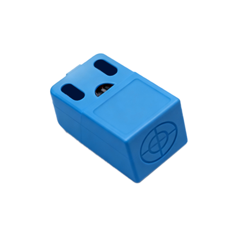
Counter-Intuitive Conclusion: A Worse Sensor Can Be a Better Sensor
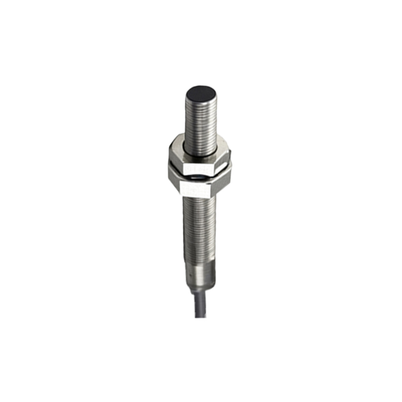
The pursuit of maximum sensitivity is often a mistake. In high-noise environments—think variable-frequency drive (VFD) rich panels or near arc welders—a less sensitive sensor, or one deliberately tuned to a lower frequency, is more robust. The high-sensitivity unit will detect the shifting electromagnetic field as a target, leading to chaos. I've consistently solved erratic behavior by swapping a "premium" 20mm range sensor for a standard 8mm version. The reduced field was less susceptible to interference. Another non-obvious insight: sometimes, you must increase the dielectric constant of the target. For reliably detecting low-εr materials like dry grains or foams, placing a fixed, thin sheet of polypropylene (εr ~2.2) behind the target area creates a stable baseline. The sensor is then tuned to detect the displacement of this known material by the target, not the target itself. This transforms an impossible application into a stable one. Finally, data shows that in packaging lines, the consistent failure point isn't the sensor element, but the PBT or PPS housing's fatigue from high-frequency vibration, leading to cracked seals. Specifying a sensor with a metal-threaded brass insert or a separate stainless-steel mounting bracket often yields a 300% longer service life than relying on the plastic housing's threads, a cost-benefit analysis rarely found in manuals.