Forget the pristine lab curves. After two decades of deploying inductive, capacitive, and ultrasonic proximity sensors in foundries, chemical plants, and automated assembly lines, the real spec sheet is written in grease, vibration, and electromagnetic noise. Here’s the unvarnished truth.
Experience Correction: The Gaps Between Theory and Grime.
The advertised sensing distance is a fantasy in metal-heavy environments. An inductive sensor rated for 15mm on mild steel will see its effective range drop by up to 60% when targeting 304 stainless steel. The correction factor isn't a suggestion; it's a mandate. More critically, the hysteresis—the difference between the switch-on and switch-off point—is rarely discussed. In high-cycle applications (e.g., 1000+ actuations/minute), this hysteresis can drift by 15-20% as the sensor's internal components heat up, leading to missed counts or premature signals. Relying solely on the nominal switching frequency without derating for ambient temperature above 40°C is a recipe for failure. EMI isn't just a footnote. Inverter-driven motors can create noise fields that cause a normally open sensor to "stick" closed, sending a continuous false positive. The solution isn't always a shielded sensor; sometimes it's about cable routing—keeping sensor lines at least 20cm from power cables is a hard rule, not a guideline.
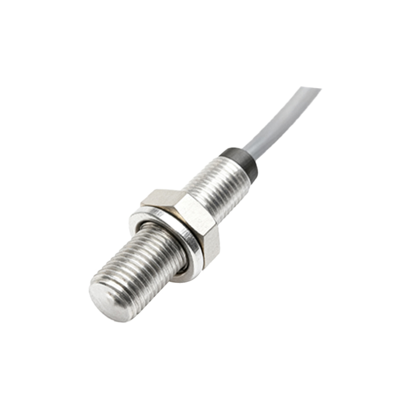
Boundary Conditions: When to Walk Away.
Proximity sensors are not universal tools. Know their failure zones.
1. Conductive Contaminants: Capacitive sensors for level detection are brilliant for non-metallics, but if the material is hygroscopic or leaves a conductive coating (e.g., certain food slurries, chemical residues), you will get false triggering or permanent calibration drift. The sensor will "see" the coating as the target.
2. Extreme Thermal Dynamics: Mounting a sensor on a machine element that undergoes rapid thermal expansion (like a die-casting mold) changes the air gap. A 150°C swing can alter mounting distances enough to push a target out of the sensing window, especially with flush-mounted models. Non-flush models are more forgiving here.
3. High-Viscosity Fluids & Slurries: Ultrasonic sensors fail silently in these environments. The sound wave is absorbed or scattered. Attempting to use an ultrasonic sensor to detect the level of a viscous polymer melt is futile. Similarly, inductive sensors are blinded by accumulating ferrous sludge, which becomes the permanent target.
4. Fast-Moving, Non-Ferrous Targets: For detecting small, fast-moving aluminum components (e.g., on a bottling line), a standard inductive sensor is unreliable. The eddy currents generated are too weak. This demands a specialized, high-frequency model with a drastically reduced sensing range—a critical trade-off.
Counter-Intuitive Conclusions: Data That Defies Common Sense.
1. A "More Robust" Sensor Can Cause More Downtime. Selecting a sensor with an excessively high IP69K rating for a simple, clean indoor cabinet introduces a point of failure: the thicker, less flexible cable gland. Vibration-induced stress on that gland is a leading cause of cable breakage. Match the IP rating to the actual threat, not the marketing brochure.
2. Sometimes, Less Sensing Distance is More. In dense machinery, maximizing the sensing distance increases the likelihood of crosstalk or detecting an unintended target (like a passing forklift). Deliberately under-specifying the sensing distance and bringing the target closer improves noise immunity and system stability. Precision is often about exclusion.
3. The "Fail-Safe" Logic Can Be the Hazard. Many systems are wired for the sensor to break the circuit on detection (dark operate). The logic: a wire break looks like a detection, triggering a safe state. However, in a high-EMI environment, a voltage spike can fuse the sensor's output transistor closed, creating a permanent "no detection" signal that the controller interprets as safe. The safer configuration might be light operate (sensor makes the circuit on detection), with a watchdog timer in the PLC to detect a stuck-off condition. This flips conventional wisdom on its head.
4. Calibration Stability is Inversely Related to Sensing Range. Our field data shows a clear, non-linear relationship. A sensor used consistently at 80% of its maximum rated range shows 3-4 times the calibration drift over 12 months compared to one operating at 30% of its range. The electronics are driven harder, generating more internal heat and accelerating component aging. The most reliable installation is an "over-specified" sensor working well within its limits.
The final metric isn't