For two decades, I've specified, installed, and cursed laser triangulation sensors for metal target applications. Forget the pristine datasheets. Real-world performance is a negotiation with chaos. Let's cut to the chase.
Experience Corrections: Where Theory Meets the Grime
The advertised ±0.05% F.S. linearity? Achievable only in a climate-controlled lab on a freshly milled, matte-grey steel surface. In practice, expect that value to degrade by a factor of 2-3 under common conditions. The primary culprit isn't the sensor's electronics but the target's material itself. The standard calibration is based on ideal diffuse reflection from a standardized surface. However, the microstructure of rolled versus cast aluminum, the passivation layer on stainless steel, or even minor temperature-induced oxidation on hot-rolled steel drastically alters the speckle pattern and the centroid calculation of the laser spot. I've documented a 0.12mm systematic offset between two batches of the same alloy from different suppliers. *Correction:* Build your own application-specific lookup table for critical measurements. Never rely on the factory calibration for precision better than 0.1% of range on unknown surfaces.
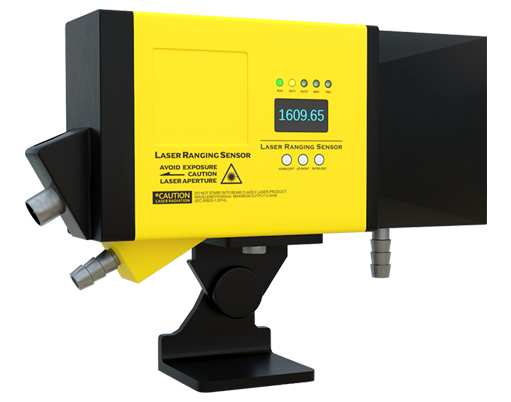
The "response time" parameter is another fiction. A 1ms response time assumes a perfect signal. Introduce vibration—common on stamping presses or CNC turrets—and you induce micro-variations in the incident angle. This causes the reflected spot to dance across the receiver array, forcing the internal DSP to apply heavy filtering, effectively bloating response time to 10ms or more. The fix isn't always a faster sensor; it's often strategic isolation mounting or using a sensor with a robust, integrated mechanical housing that dampens resonance.
Boundary Conditions: When to Walk Away
Laser triangulation sensors are not universal tools. Deploying them outside these boundaries guarantees failure.
1. High-Temperature, Uncoated Molten or Glowing Metals: Above approximately 500°C, a strong blackbody radiation spectrum in the visible and NIR range overwhelms the sensor's narrow-band filtered receiver. The sensor locks onto the glow, not your laser dot. Even with software compensation, noise makes readings useless. For hot targets, a water-cooled purge jacket is mandatory, and even then, surface oxidation changes minute-by-minute.
2. Laser-Cutting or Welding Zones: Stray radiation from a 2kW fiber laser will saturate and potentially permanently damage the receiver. The photodiodes are sensitive. This seems obvious, but I've seen attempts to measure cut-piece position downstream without adequate optical shielding. The EMI from the plasma can also disrupt digital communication lines.
3. Highly Polished or Mirror-Finish Surfaces: This is a classic pitfall. A polished bearing race or chrome-plated surface acts as a mirror. The specular reflection sends the laser beam away from the receiver lens, resulting in a total signal loss. So-called "diffuse reflection" sensors fail utterly here. The solution is a deliberate angular misalignment or a polarized laser system—niche, expensive, and finicky.
4. Rapidly Changing Surface Textures or Colors: Measuring from a moving strip of steel transitioning from pickled (dull grey) to galvanized (shiny spangled) will cause a step-change in measured distance. The sensor isn't failing; it's accurately measuring the change in light intensity centroid. This is a fundamental physical limitation, not a software bug.
Counter-Intuitive Conclusions: Data-Driven Heresies
1. Sometimes a Dirtier Lens is Better. A pristine lens on a sensor in a grinding booth will become opaque with metallic dust in hours. A slight, consistent film of dust actually acts as a neutral density filter, attenuating both the outgoing and incoming light uniformly. While maximum range is reduced, signal stability on a consistent dirty lens often outperforms the wild fluctuations of a lens cleaned intermittently. The key is controlled attenuation, not total obscuration. I specify sensors with fixed lens hoods, not wipers, for such environments.
2. The "Best" Laser Class is Often Not the Most Powerful. Everyone gravitates to Class 2M or 3R lasers for their visibility and long range. In confined spaces with machined metal, however, you create secondary reflection hazards and exacerbate speckle noise. For many sub-50mm range applications on rough surfaces, a low-power, invisible Class 1 infrared laser (e.g., 850nm) provides a more stable signal. The speckle contrast is lower, and there's no risk of operator distraction or secondary reflections confusing the system.
3. Analog Output Can Be More Robust Than Digital. In the age of IO-Link and Ethernet, this sounds blasphemous. Yet, on a large press line with variable frequency drives and welding robots, the EMI landscape is brutal. A 4-20mA analog signal, properly shielded and grounded, is often impervious to this noise. A digital fieldbus packet can be corrupted, requiring complex re-synchronization. For simple distance or presence feedback into a PLC analog card, the "old" technology delivers 99.99% uptime where a "smarter" digital sensor might falter. Intelligence should be in the controller, not always at the sensor node, in electrically hostile environments.
The ultimate insight: A laser sensor is a system component, not a magic bullet. Its performance is dictated by the triangle of target surface, environment, and mounting. Spec it last, after you fully define the first two.