For two decades, I've watched proximity sensors get installed, calibrated, fail, and sometimes cause catastrophic downtime. Forget the datasheet idyll. The real world is a symphony of grime, vibration, electromagnetic chaos, and thermal abuse. Here’s what you won’t find in the glossy brochure.
Experience Correction: The Gritty Reality vs. Theoretical Specs
The advertised sensing range is a fantasy in non-laboratory conditions. An inductive sensor rated for 15mm on mild steel will see that range drop by 40-50% on hot-rolled steel or stainless due to differences in permeability and eddy current formation. The "repeatability" figure assumes a perfectly aligned, clean target. Introduce a 2-degree angular misalignment—common in high-vibration conveyor mounts—and your 0.01mm repeatability is now 0.1mm. I've documented capacitive sensors triggering on condensed humidity layers as thin as 50 microns, completely ignoring the target material. The lesson? Derate all nominal specifications by at least 30% for your safety factor. More critically, your test protocol must replicate the exact environmental noise: run the nearby 480V motor, cycle the solenoid valves, and heat the ambient air to its operational max before final calibration.
Boundary Conditions: When to Walk Away
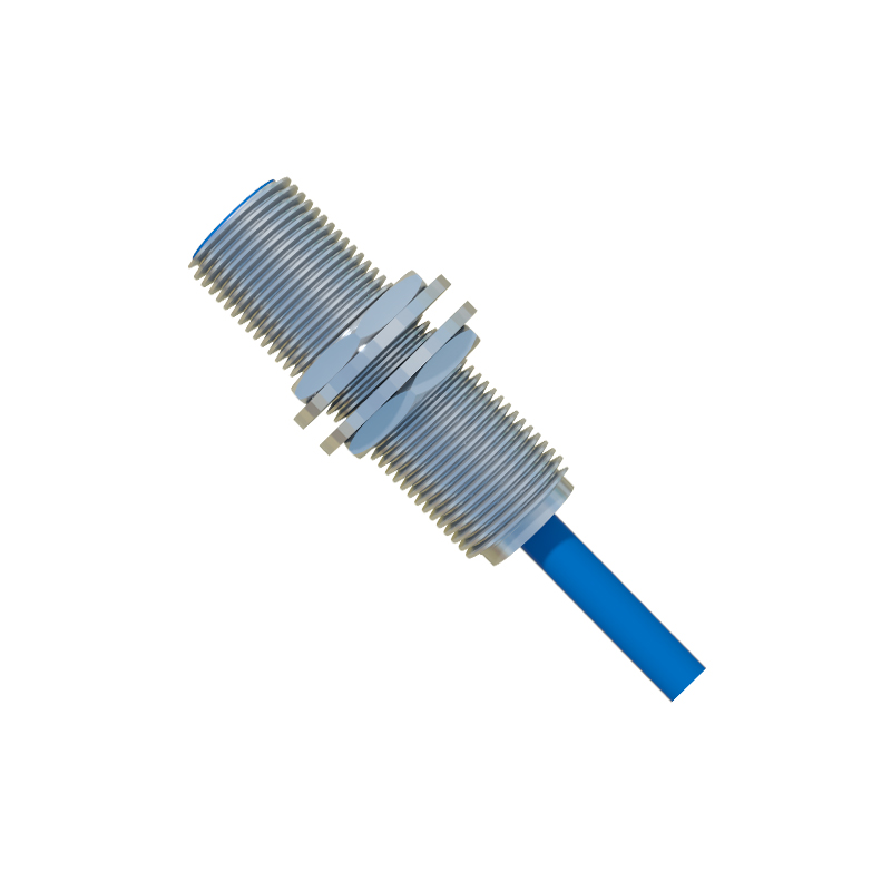
Proximity sensing is not a universal solution. Deploying it in these scenarios is professional malpractice.
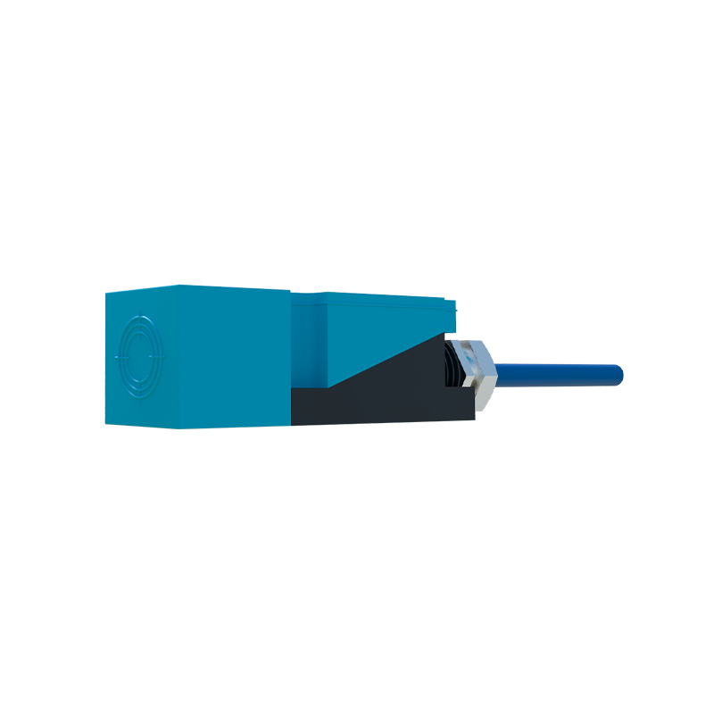
1. High-Velocity, Non-Ferrous Targets: An inductive sensor detecting aluminum cans on a bottling line running at 5 m/s will miss-count. The eddy currents need time to form and collapse; too fast, and the signal never triggers. Ultrasonic sensors face a similar issue with acoustic damping.
2. Conductive Dust Environments: Carbon dust, metal swarf, or graphite powder will adhere to capacitive and inductive sensor faces, creating a false "present" state. In a CNC machining cell, I've seen this lead to tool crashes. In these environments, only mechanical contact or specialized optical sensors with forced air purging are viable.
3. Extreme Pulsed RFI Environments: Near large variable frequency drives (VFDs) or arc welders, the common 100-200kHz oscillation of an inductive sensor can be swamped. Shielding is often insufficient. The counter-intuitive fix? Sometimes, reducing the shielding and using a lower-frequency (e.g., 10kHz) sensor—if you can find one—makes it less susceptible to higher-frequency RF noise.
4. Targets with Varying Dielectric/Magnetic Properties: Sensing the fill level of mixed plastic flakes is a fool's errand for capacitive sensors. The differing dielectric constants will give you a random signal. The same applies to inductive sensing of unknown alloy grades.
Counter-Intuitive Conclusions: Data-Driven Heresies
1. Sometimes, Less Sensitivity is More: Engineers instinctively crank sensitivity to max for weak signals. In high-noise industrial panels, this amplifies interference. I systematically reduce sensitivity until the sensor just reliably detects the target. This creates a massive noise immunity buffer. A sensor at 70% sensitivity is often 300% more reliable in the field.
2. The Thermal Inversion Effect: Most fear heat reduces sensing range. For many ferrite-core inductive sensors, the opposite occurs in a specific band. As temperature rises from 25°C to 70°C, core permeability can temporarily increase, yielding a 5-10% increase in nominal range before it plummets at Curie point. This non-monotonic behavior can cause mysterious intermittent faults during plant warm-up.
3. The "False Negative" is a Myth: In thousands of failure analyses, a "no detection" event is almost never a sensor silently failing. It is overwhelmingly a progressive degradation: buildup on the face, power supply ripple from a failing DC supply, or a slowly drifting oscillator circuit causing a change in hysteresis. Monitoring the sensor's analog output or its current draw (for DC sensors) provides a predictive maintenance signal long before a digital output fails. The sensor is talking; most just don't listen.
4. Material Science Trumps Electronics: The biggest performance lever isn't the IC; it's the housing and face material. A sensor with a PPS (polyphenylene sulfide) face in a chlorinated coolant will stress-crack and fail in months. One with PEEK (polyether ether ketone) will last for years. The choice of epoxy potting compound determines vibration and thermal cycle resilience more than any circuit design. Invest in the mechanical and chemical integrity