Forget the pristine data sheets. The real game in proximity sensor installation isn't about achieving the nominal sensing distance (Sn); it's about mastering the delta between the lab and the field. After two decades of deploying millions of sensors in automotive welding, food processing slurry, and mining vibration, I've learned that the published spec is merely a starting point for negotiation with reality.
Experience Correction: The Harsh Reality vs. Theoretical Sn
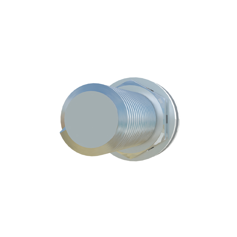
The textbook states a 10mm inductive sensor has a 10mm Sn. In practice, expect 7-8mm, and consider yourself lucky. The primary corrosive agent isn't chemicals, but time and particulate matter. In a stamping plant, airborne metallic dust forms a conductive film on the sensor face, effectively creating a parasitic shield. This can reduce effective sensing distance by up to 30% within a week. The countermeasure isn't more frequent cleaning—that introduces downtime. It's about specifying a sensor with a 50% higher nominal Sn than theoretically required and implementing a flush-mounted design wherever possible, even if it complicates the mechanical layout. Another critical deviation: target material. Mild steel is the calibration standard. For 304 stainless steel, derate the effective Sn by 25-30%. For aluminum, expect a 40-50% reduction. If your system uses multiple materials, tune for the worst-case scenario, not the average.
Boundary Conditions: When to Walk Away
Proximity sensors are not universal solutions. Their failure in certain contexts is not a malfunction but a physics inevitability.
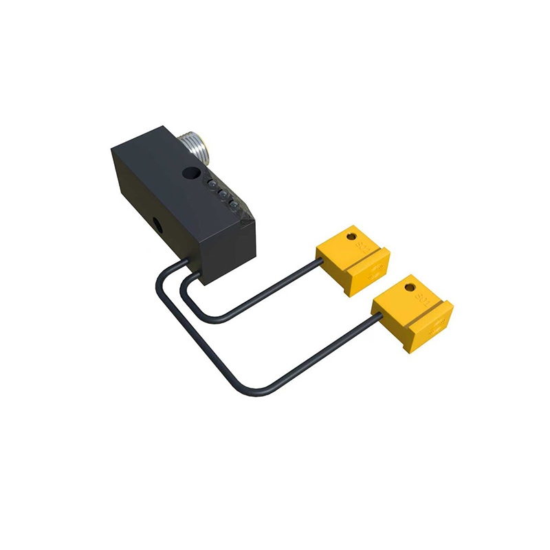
1. High-Speed Non-Ferrous Targets: Detecting aluminum cans on a conveyor at 3+ meters/second is a recipe for missed counts. The eddy currents generated are weak and slow to form relative to the target's passage. Here, photoelectric sensors are the only viable choice, despite their sensitivity to contamination.
2. Extreme Electromagnetic Noise Environments: Near large VFD-driven motors (especially older generation) or arc welders, the sensor's oscillator can lock onto the external noise. The result isn't intermittent failure but a consistently "on" state, a dangerous fail-closed condition. Shielding is often futile. The boundary is clear: if you can measure EMI above 50V/m in the 100kHz-1MHz range, use a fully analog sensor with a high-current output or opt for a pneumatic limit switch.
3. Thin or Small Targets: The "effective target" rule is often misapplied. For a standard 18mm diameter sensor, the textbook says the target should be at least the sensor's face diameter. In truth, for reliable detection, the target's thickness is more critical than its width. A thin foil, even if wide, may not generate sufficient mass to trigger the sensor reliably. If the target thickness is less than 10% of the sensor's Sn, abandon the inductive approach.
Counter-Intuitive Conclusions: Data-Driven Heresies
1. Increased Sensing Distance Can Lower Reliability. Chasing the longest possible Sn for a safety margin seems logical. However, an excessively large Sn increases the sensor's "field of view," making it susceptible to detecting unintended background objects like moving machinery or structural supports. This causes false triggers. The optimal installation is at 80-90% of the derated, real-world Sn, not 60-70% as commonly taught. This tightens the detection field and improves noise immunity.
2. Warm-Up Time Matters for Precision Applications. The oscillator circuit's frequency drifts with temperature. In a climate-controlled lab, this is negligible. In an unheated warehouse where ambient temperature swings 15°C from startup to midday, the Sn can shift by 5%. For high-precision positioning (e.g., robotic tool change), allow a 15-minute operational warm-up cycle before enabling critical processes. This is rarely documented.
3. The "Fail-Safe" Output is Often the Less Safe Choice. Many sensors offer an N.O./N.C. selectable output. The instinct is to choose the normally closed (N.C.) circuit for safety, so a wire break causes a shutdown. However, in modern PLC-based systems, a broken wire on an N.C. sensor reads as a "target present" signal. If this is monitoring a guard door, the system thinks the door is closed when it's not. A robust system using N.O. sensors, combined with a pulsed watchdog circuit monitored by the PLC, provides a higher integrity safety loop. This contradicts classic relay logic but is imperative for modern controls.
The final metric is not installation distance, but mean time between false signals (MTBFS). Optimize for that.