Forget the pristine curves in the application notes. After two decades of deploying proximity sensors in mining, chemical processing, and high-speed automation, the real design begins where the datasheet ends. The core challenge isn't selecting a sensor, but engineering a circuit that survives the real world. Here’s the uncompromising analysis.
Experience Correction: The Illusion of Stable Parameters.
The stated sensing distance and repeatability are laboratory fantasies. In practice, three factors dominate performance deviation. First, ground plane noise is systemic. A standard 12mm inductive sensor specified for 4mm range will see its effective sensing distance shrink by up to 35% when mounted on a vibrating steel frame without a localized, star-point ground for its shield wire. The common "two-wire" DC design is particularly vulnerable, often requiring a 40-50% derating in claimed range for reliable operation. Second, temperature coefficients are non-linear. While a datasheet lists a ±10% drift from -25°C to 70°C, the critical failure mode is the hysteresis shift in the Schmitt trigger stage during rapid thermal cycling. This can cause a 20% change in the switch-point differential (the difference between "on" and "off" points), leading to chatter on conveyor edges in foundries. Third, load dump and back-EMF are circuit killers. Driving a small relay coil directly from the sensor output? The inductive kickback will, without exception, degrade the output transistor’s lifespan. The solution isn't just a flyback diode; it's a calculated RC snubber across the load, with values determined by the relay's coil inductance and the circuit's inductance, not generic tables.
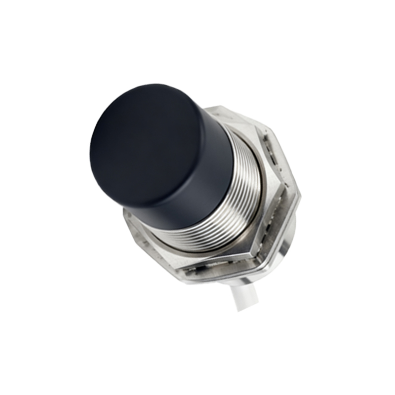
Boundary Conditions: Where This Technology Fails.
Proximity sensing is not a universal solution. Its application boundaries are stark. Conductive dust and slurries are a hard stop. Inductive and capacitive sensors will fail catastrophically in environments like coal handling or pulp processing. The media coats the sensing face, creating a permanent false trigger or dead zone. Here, ultrasonic or ruggedized through-beam photoelectric sensors are the only viable options, despite higher cost and complexity. High-speed ferrous targets on non-ferrous backgrounds present a subtle trap. An inductive sensor targeting rapidly passing steel bolts on an aluminum frame will detect the massive aluminum background as its "reference" state. The small change from the passing bolt can be lost in the noise, causing intermittent misses. This scenario demands a differential or background suppression sensor type, a specification often overlooked in favor of standard units. Finally, any circuit using a "universal" AC/DC power supply module is a liability. The switching noise from these supplies injects high-frequency hash into the sensor's oscillator, causing erratic behavior with metallic flakes or coolant mist. A linear regulated supply or a properly filtered DC source is non-negotiable for stability.
Counter-Intuitive Conclusions: Data That Defies Convention.
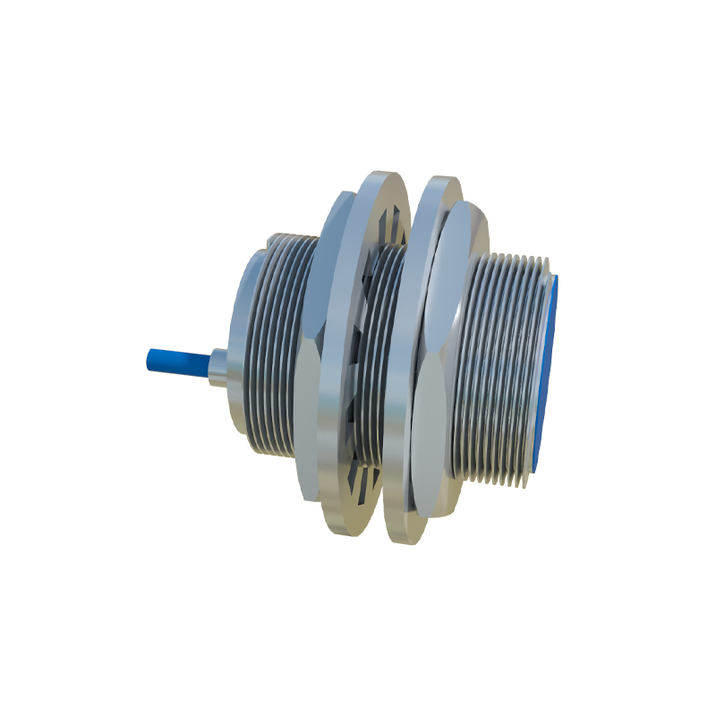
1. More Shielding Can Reduce Performance. A fully shielded sensor body is marketed as superior. However, when mounted flush in a metal bracket, the eddy currents generated in the shield can create a "dead zone" that reduces the effective switching frequency by up to 30% for fast-moving targets. For detecting small, fast parts (e.g., nuts on a vibratory feeder), an unshielded or partially shielded sensor often provides a more robust and higher-frequency response, despite being more susceptible to lateral metal interference.
2. The "Better" Output Type Increases Failure Risk. Sourcing (PNP) outputs are often preferred for modern PLCs. Yet, in 24V systems, a single wire short to ground on a PNP output will fry the sensor's output stage. A sinking (NPN) output, in the same fault condition, will typically only pull the line low, often causing a safe machine stop. In harsh environments where cable damage is probable, designing the safety loop to utilize NPN outputs can dramatically increase mean time between failures (MTBF).
3. Analog Outputs Are More Reliable for Digital Tasks. The instinct is to use a digital on/off sensor for position verification. However, in applications with variable target sizes or positions (e.g., warped metal sheets), a 4-20mA analog output connected to a comparator circuit provides a more reliable "go/no-go" signal. The analog signal allows you to set a precise, noise-resistant window in the circuit, filtering out false triggers from debris or vibration that would plague a digital sensor operating at its threshold limit.
The final circuit schematic is less about connectivity and more about defensive countermeasures. It must include calculated snubbers, local decoupling capacitors (100nF ceramic in parallel