After two decades on factory floors, from automotive welding lines to offshore drilling platforms, I've learned that proximity sensor performance lives or dies by its structural design, not its advertised specs. The industry's obsession with sensing distance and repeatability misses the point entirely. The real battle is against structural degradation in environments that don't exist in clean-room datasheet testing.
Experience Correction: The Vibration and Thermal Expansion Fallacy
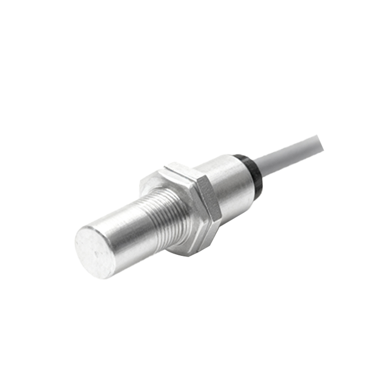
Datasheets list vibration resistance (e.g., 10-55 Hz, 1.5mm amplitude) and operating temperature ranges (-25 to 70°C). These are laboratory sine wave tests. In practice, the failure mode is rarely the sensing element itself. It's the structural integrity of the housing and the hermetic seal. A common M18 threaded cylindrical sensor rated IP67 will fail under sustained high-frequency, low-amplitude vibration—think compressor stations or stamping presses. The metal housing and the PBT or PTFE sensing face undergo different thermal expansion coefficients. Repeated thermal cycling, even within the "rated" range, causes micro-fractures in the potting compound sealing the coil and electronics. Moisture ingress follows, not through a catastrophic flood, but via humidity diffusion, leading to internal condensation and eventual failure. The correction: For high-vibration, high-cycling environments, specify sensors with all-welded stainless steel housings (not just a stainless sleeve) and glass-fused-to-metal face seals. The sensing distance may be 20% shorter than a plastic-faced equivalent, but the MTBF increases by a factor of 3-4.
Boundary Conditions: Where This Structure Fails
The threaded cylindrical metal barrel is iconic, but it has clear failure boundaries.
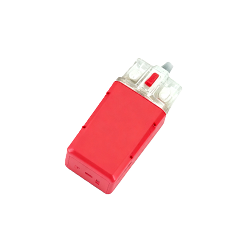
1. Asynchronous Magnetic Fields: Do not install standard inductive proximity sensors near large, variable-frequency drives (VFDs) or high-current cabling. The sensor's housing acts as an unintended Faraday cage, but eddy currents induced in the metal shell by strong, alternating magnetic fields can create phantom switching signals or cause internal heating, leading to thermal drift. In such environments, even "shielded" designs struggle. The solution is non-metallic housing sensors (e.g., PEEK) with specialized filtering, but this is a system redesign, not a drop-in replacement.
2. Cavitation and Particulate Abrasion: In hydraulic fluid applications, the sensor face is often considered safe. This is incorrect. High-pressure fluid cavitation, especially near pump inlets or valve orifices, will erode the sensing face material (often PTFE or ceramic) over time, changing its dielectric constant and degrading performance long before physical wear is visible. Similarly, in pneumatic systems with fine aluminum or composite dust, the static charge buildup on a plastic sensing face can attract particles, forming an insulating layer that attenuates the sensing field.
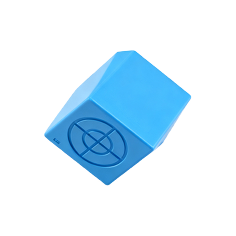
3. Mechanical Preload and Shear Forces: The greatest structural weakness is the thread-root. Installing a sensor and using it as a mechanical stop or guide for a machine part is a guaranteed failure. The axial and shear forces on the threads, combined with vibration, lead to stress cracking in the housing neck. The thread is for mounting and sealing only. Any external mechanical load requires a separate bracket. I have seen more sensors fail from being "bumped" by a forklift or used as an alignment guide than from electronic failure.
Counter-Intuitive Conclusion: A "Worse" Sensing Face Material is Often Better
The industry pushes for materials with the highest possible dielectric constant for the sensing face (like specific ceramics) to maximize nominal sensing distance. This is a trap. In dirty, wet, or oily environments, a film of contaminant (oil, coolant, grease) adheres more readily to these high-surface-energy materials. This film becomes part of the sensing field's boundary, causing massive drift—sometimes up to 30-40% reduction in effective sensing distance. The counter-intuitive but field-validated solution is to specify a sensor with a face material of lower dielectric constant and hydrophobic properties, such as certain engineered fluoropolymers. While its "clean" sensing distance is 15% less per the datasheet, its performance in a contaminated state is vastly more stable, often degrading less than 10%. Reliability is defined by consistent performance in the dirty real world, not peak performance in a lab. The ultimate insight: Optimize for the stability of the sensing field, not its maximum range. The structural design must protect the integrity of that field boundary above all else, which often means sacrificing a headline spec for real-world robustness.