For two decades, I've watched pristine spec sheets meet greasy, vibrating, thermally hostile reality. The gap between lab performance and field survival is where real engineering happens. Forget the marketing fluff. Let's talk about what actually matters when your laser-based load measurement system is on the line.
Experience Correction: Where Theory Meets the Grinder
The advertised ±0.05% F.S. accuracy? Achievable only in a controlled, 72°F environment with a perfectly aligned, clean target. In practice, thermal drift of the laser diode itself is the silent killer. A 10°C swing in ambient temperature near the sensor head can induce a 0.1-0.2% zero-point shift, a error often misattributed to mechanical creep. Vibration is another theorist's blind spot. High-frequency, low-amplitude vibration—common near motors or conveyors—doesn't just add noise; it causes micro-deflections in the internal optical path, leading to non-linear hysteresis in the output. You can't filter it out with software. The fix? Empirical characterization under *real* vibration spectra, not just ISO standard tests, followed by strategic internal damping and a hardened mechanical design that prioritizes stiffness over minimalism.
Boundary Conditions: When to Walk Away

Laser load cells are not universal soldiers. Deploying them in these scenarios is professional malpractice. First, environments with high particulate density (e.g., flour mills, coal handling). Particles settling on the laser window or the reflective target cause signal attenuation that mimics a load increase. Purge systems fail when coatings become adhesive. Second, applications involving highly reflective or specular surfaces. The common assumption is that more reflection is better. Wrong. A mirror-like surface can create multiple reflection paths, causing phase cancellation and drastic signal dropout with minute angular changes. Third, dynamic weighing of non-rigid bodies (e.g., slurries in a moving vessel). The laser measures distance to a surface that is sloshing. The load calculation assumes a static plane. The resulting data is a fiction of fluid dynamics, not a mass measurement. In these cases, a robust shear beam or hydraulic cell, despite lower "paper" precision, is the superior choice.
Counter-Intuitive Conclusion: Sometimes a Dumber Sensor is Smarter
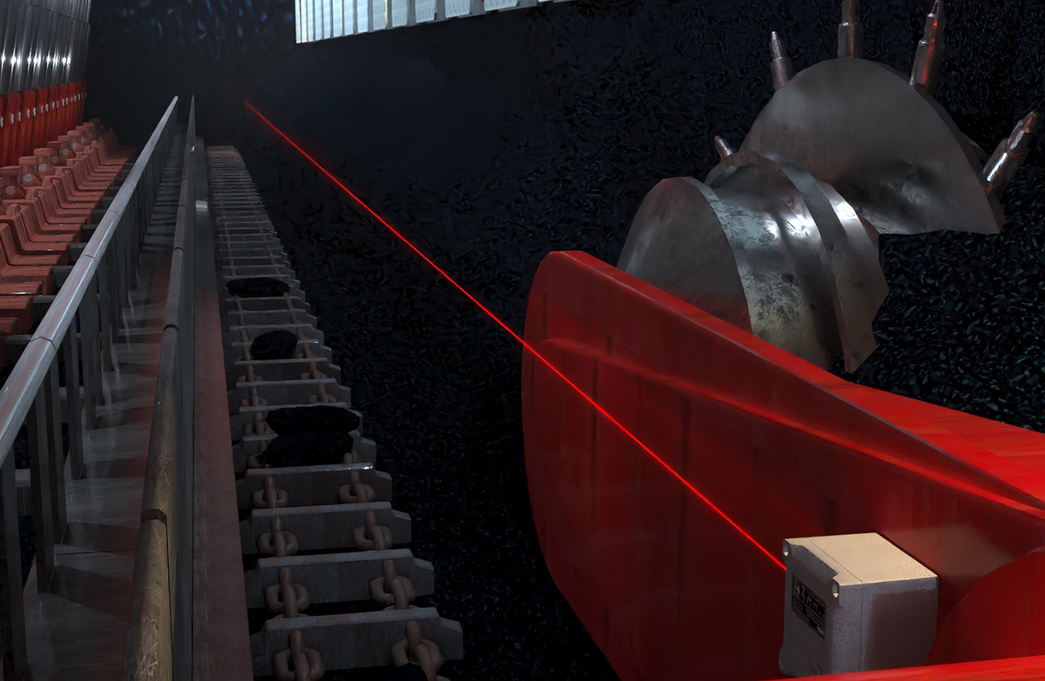
Here’s the heresy: Chasing higher laser resolution (e.g., from 1µm to 0.1µm) for static or slow-moving loads is often a waste of capital and a source of instability. The limiting factor is rarely the laser's resolution but the structural stability of the entire system—the foundation thermal mass, the stiffness of the support structure, the thermal expansion of the target plate. Investing a $10,000 premium on a sub-micron laser is futile if a $2,000 sunshield and a properly engineered concrete plinth improve measurement repeatability by an order of magnitude more. Furthermore, over-sampling high-resolution data in industrial environments simply gives you a higher-fidelity record of noise. The key insight is to match the sensor's *precision* to the *practical stability* of its installed environment. Often, a "less capable" laser with superior temperature compensation and ruggedized construction outperforms a fragile lab-grade unit in the field. Your system is only as accurate as its weakest environmental coupling, not its most impressive sub-component spec.
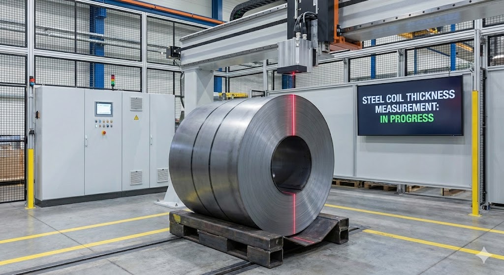
The bottom line: Success with laser sensor load cells is 30% about understanding the sensor and 70% about rigorously diagnosing and defending against the real-world environment it must live in. Specs are a starting point for a conversation, not a guarantee of performance. Design for the chaos.