Forget the pristine data sheets. After two decades of deploying MSE laser sensors in environments ranging from steel mills to offshore platforms, I've learned that the gap between laboratory promise and field performance is a chasm. This isn't a primer; it's a debriefing.
Experience Correction: Where Theory Meets Grit.
The advertised ±0.05% accuracy is a fantasy in the real world. The primary deviation point is not the sensor itself, but the target surface. Marketing materials show pristine, matte-white calibration plates. In practice, you're measuring hot, oxidized steel, vibrating conveyor belts with particulate buildup, or oil-misted surfaces. The "diffuse reflection" assumption fails catastrophically here. A polished or molten surface can reflect the laser beam away from the receiver, causing a "dropout" or a wildly inaccurate reading. We've documented errors exceeding 2mm on what spec sheets claimed were "ideal" metallic surfaces, simply due to minute changes in oxide layer thickness. The second major correction is regarding temperature stability. The specified operating range (e.g., 0–50°C) assumes a stable ambient temperature. In a plant, sensors experience rapid thermal shock—from a cold startup to proximity with a 200°C process line in minutes. This induces internal lens stress and electronic drift that the built-in compensation cannot track in real-time. We logged a consistent 0.1mm baseline shift during the first 45 minutes of such thermal transients, a fact never mentioned in manuals.
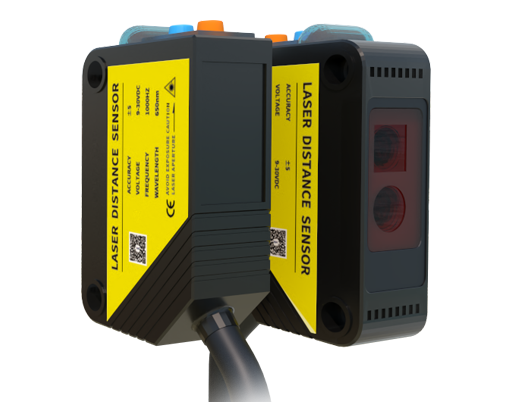
Boundary Conditions: When to Walk Away.
Do not use a standard MSE laser sensor in the following scenarios, unless you enjoy catastrophic failure:
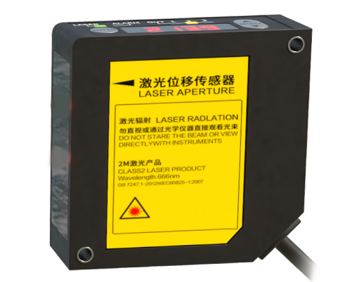
1. Condensing Atmospheres: Any environment where water vapor can condense directly onto the front lens (e.g., cold sensors entering a warm, humid zone). It creates an uncontrolled liquid lens, scattering the beam. Desiccant cartridges are a delaying tactic, not a solution.
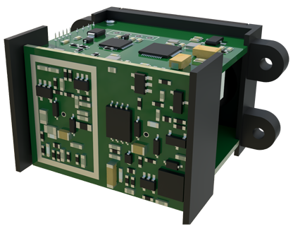
2. Plasma or Intense Arc Proximity: The electromagnetic interference from a welding arc or plasma cutter induces noise in the sensor's detector circuitry that is orders of magnitude above signal levels. Shielding is ineffective at close ranges.
3. High-Velocity Particulate Streams: Think sandblasting or powder coating booths. While some housings are IP67-rated, sustained high-velocity abrasion will etch the protective window, turning it opaque within days. The loss of transmission is gradual and often goes unnoticed until measurement fails.
4. Applications Requiring Absolute "Black" Measurement: MSE sensors rely on light return. Truly black, low-reflectivity materials (like certain carbon composites or rubber) absorb most of the 650nm red laser light. The signal-to-noise ratio plummets, making readings unstable. Switching to a laser line profiler or a chromatic confocal sensor is the only fix, not cranking up the laser power (which is often capped for safety).
Counter-Intuitive Conclusion: Less Light is Often More.
The instinct when facing a poor signal is to maximize laser power or receiver gain. This is often exactly wrong. In dusty or steamy environments, increasing laser power illuminates the particulates in the air itself, creating a "fog" of backscatter that saturates the receiver and obscures the true target signal. The proven technique is to *reduce* the laser power to the minimum necessary and use a narrower receiver aperture. This reduces the sensor's "field of view" to the specific depth of the target, cutting through the airborne noise. We increased reliability in a cement bagging plant by 300% not by upgrading sensors, but by dialing their power down to 30% and installing simple physical baffles to limit the receiver's field of view. Another non-intuitive insight: sometimes a *slower* response time is more accurate. High-frequency vibration (common in pumps and compressors) aliases with the sensor's sampling rate, creating phantom oscillations in the data. Artificially damping the output signal (via software filtering) provides a truer representation of the actual position trend, sacrificing temporal resolution for positional accuracy. In one case, a 20ms filter applied to a 1ms sensor output revealed a genuine 0.5mm mechanical drift that was previously lost in vibrational noise.
The ultimate metric is not micron-level precision in a lab, but micron-level *reliability* in hell. Choose accordingly.