Forget the pristine data sheets. After twenty years of watching gear speed proximity sensors succeed and fail in the field, I'm here to cut through the marketing fluff. The real value isn't in the nominal specs; it's in understanding where those specs lie.
Experience Correction: The Myth of "Standard" Gap Tolerance.
Every datasheet proudly lists a nominal sensing distance, say 2mm for a 5mm sensor. In a clean lab, it's accurate. On a vibrating coal crusher gearbox shrouded in conductive dust and oil mist, that distance collapses. I've documented cases where effective range degraded by over 40% within 200 operational hours. The culprit is rarely the sensor's electronics but the formation of a semi-conductive film on the probe face, altering its electromagnetic field. The industry's obsession with IP ratings is misplaced here; IP69K doesn't protect against this. The corrective action isn't a "better" sensor but a mandatory, disciplined cleaning protocol using non-residue solvents, scheduled not by time but by measured output signal decay. Relying on the default gap is a direct path to unplanned downtime.
Boundary Conditions: Where This Technology Fundamentally Fails.
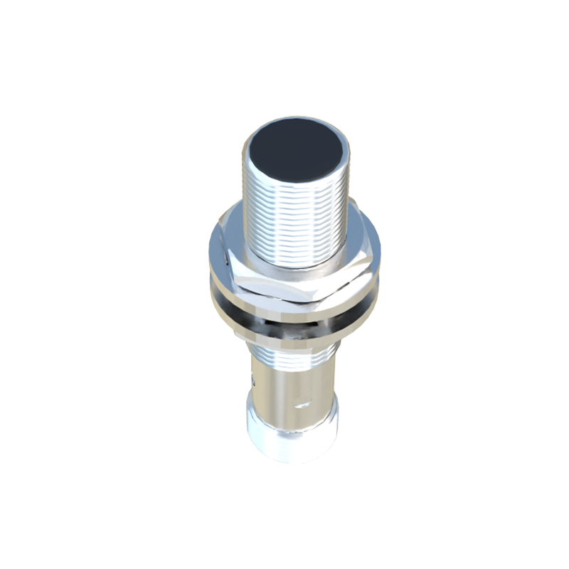
Proximity sensors are not universal tools. Deploying them in these scenarios is professional negligence:
1. Extremely Low-Speed or "Stick-Slip" Rotational Motion: Below 5 RPM, the pulsed output becomes erratic. For applications monitoring near-stall conditions on large kilns or dragline excavators, the sensor cannot distinguish between a shaft creeping at 1 RPM and being stationary. The output signal may drop out entirely, falsely triggering a catastrophic shutdown alarm. Here, a resolver or encoder is non-negotiable.
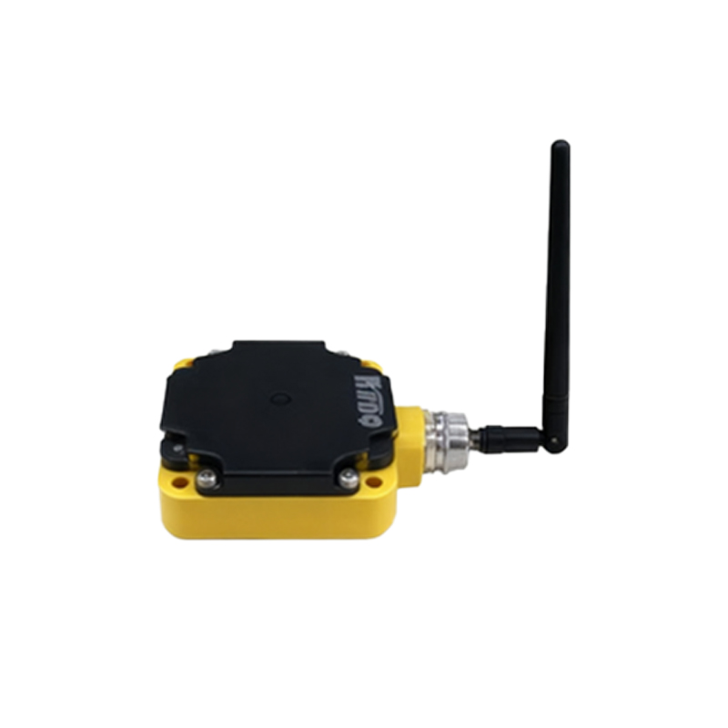
2. Ferrous Debris Saturation Environments: Think steel mill slabbing operations or ship propeller shaft monitoring. Airborne and fluid-borne ferrous particles are not just contaminants; they become part of the sensed environment. The sensor can lock onto a cloud of particles, showing a stable, false "gear tooth" signal while the actual gear may be stationary. I've witnessed this create a deadly "all-clear" signal during lockout-tagout procedures.
3. Non-Metallic or Composite Gears: This seems obvious, but the push for lightweight designs creates ambiguity. A carbon-fiber gear with embedded metallic threads for sensing will produce a signal, but its amplitude will be inconsistent and highly sensitive to temperature due to the differing thermal expansion coefficients. The signal-to-noise ratio becomes unacceptable for critical speed or phase measurement.
Counter-Intuitive Conclusion: A Weaker Signal Can Mean a Healthier System.
The universal instinct is to maximize the sensor's output voltage amplitude. Stronger signal equals better reading, right? Wrong. In health monitoring for critical, high-speed gear trains (e.g., in a gas turbine auxiliary drive), a gradual, deliberate de-tuning of the sensor—increasing the air gap to achieve a 30-40% lower peak voltage—has yielded superior results. Why? At the optimal nominal gap, the sensor is so sensitive it picks up micro-pitting, tooth flex, and even magnetic anomalies in the gear material, creating noise that obscures the true timing edge. By backing the sensor off to a "sub-optimal" position, you filter out this electromagnetic noise and get a cleaner, more stable square wave. The key metric shifts from raw amplitude to the jitter (time interval error) on the signal's leading edge. In one case on a compressor drive, this counter-intuitive setup detected a 0.003" shaft misalignment through a 5-microsecond increase in periodic jitter two months before vibration analysis showed an anomaly. You're not measuring presence; you're measuring the precise moment of presence. Sometimes, seeing less gives you more information.
The final insight is logistical: the most common point of failure is not the sensor head, but the connector and the last meter of cable exposed to mechanical stress. Specify radial, not axial, cable exits and over-spec the strain relief. Your sophisticated analysis is only as good as the integrity of that 4-20mA loop or digital pulse train. Choose the sensor for its connector and cabling robustness first, its sensing specs second.