Forget the datasheet. After twenty years of deploying proximity sensors in environments ranging from foundry floors to offshore rigs, I operate on a different set of rules. The glossy brochures and ideal-condition specifications are a starting point, but the real knowledge is written in the grime of sensor failures and the cost of unplanned downtime. Here is the uncompromising breakdown.
Experience Correction: The Gritty Reality vs. Theoretical Specs
The most pervasive myth is the stated sensing distance. In a clean lab, an inductive sensor might achieve its rated 15mm. Introduce target material variance—say, a different grade of stainless steel (304 vs. 316)—and you can lose up to 30% of that range. For capacitive sensors touted for liquid level detection, the dielectric constant is king. A fluid change from water (ε≈80) to hydraulic oil (ε≈2-5) doesn't just tweak performance; it can render the sensor completely blind unless meticulously recalibrated on-site. Temperature isn't a linear derating curve; it's a killer. A sensor rated for 70°C will see its internal oscillator drift and its output transistor leakage current spike exponentially as it approaches that limit in a sealed control cabinet with no airflow, leading to ghost signals. The real-world sensing distance is the rated distance, multiplied by a factor of 0.7 for material, 0.8 for temperature, and 0.9 for mounting surface conductivity. Do the math. You're already operating at half-capacity.
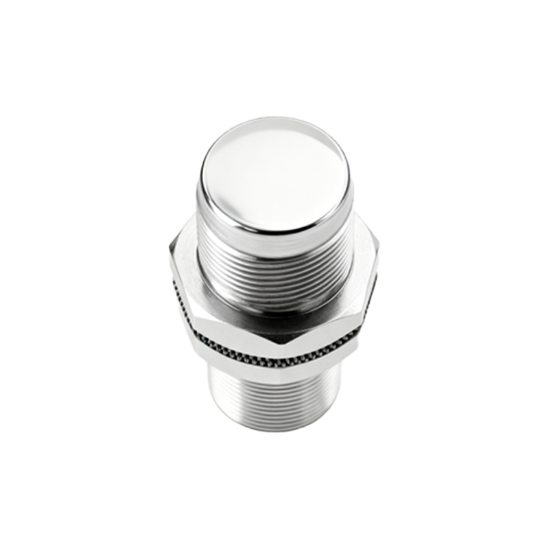
Boundary Conditions: Where to Walk Away
Knowing when not to use a technology is more critical than knowing how to use it.
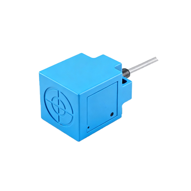
1. Ferrous Dust & Swarf Environments: Inductive sensors are magnets for fine ferrous particulate. The dust accumulates on the active face, gradually dampening the electromagnetic field until sensing fails. No amount of IP69K rating prevents this; it's a physics problem. Here, ultrasonic sensors or physically isolated reed-proxy systems are the only viable options, despite their slower response.
2. High-Speed Non-Ferrous Targets: Need to detect aluminum cans at 2000 units per minute? Standard inductive sensors will struggle with the weak eddy currents. The "solution" of increasing frequency for faster response has a dark side: drastically increased sensitivity to airborne EMI from VFDs and welders, causing erratic operation. This is a fundamental trade-off, not a solvable flaw.
3. Condensing Atmospheres & Rapid Thermal Cycling: Capacitive and ultrasonic sensors loathe condensation. A water film on the diaphragm or face permanently alters the dielectric or acoustic impedance, causing drift and false triggers. If your process cycles from 5°C to 50°C hourly, no housing seal can keep up. This is a hard boundary. Move to a contact or mechanical method.
4. Extreme Vibration (>15g constant): Internal solder joints and potted electronics fatigue. The failure mode isn't sudden death but intermittent operation—the most expensive kind to diagnose. Vibration-rated models exist, but their cost often exceeds building a decoupled, remote sensing assembly.
Counter-Intuitive Conclusions: Data-Driven Heresies
1. Sometimes, Less Sensing Distance is Better. In high-vibration or target-rich environments, deliberately selecting a sensor with 50% of the "required" range can eliminate false triggers from background objects. Stability trumps theoretical capability. A 5mm sensor locked onto a target is infinitely more reliable than a 20mm sensor chattering.
2. The "Fail-Safe" Output is Often the Point of Failure. DC 3-wire sensors with NPN Normally Open (NO) outputs are lauded as "fail-safe" (open circuit on failure). In reality, a severed cable on an NPN NO sensor appears as a permanent "target not present" signal—a dangerous state for many machine guards. A PNP Normally Closed (NC) configuration, where a wire break causes the output to go low (target present), can force a machine into a safe state. True safety requires analyzing the failure mode of the entire circuit, not the sensor's marketing label.
3. Shielding Can Make EMI Problems Worse. Facing EMI noise, the instinct is to specify a shielded sensor. However, in dense installations, the grounded metal shield can capacitively couple with adjacent sensors, causing crosstalk. Unshielded sensors, when properly spaced (≥2x sensor diameter), often perform more reliably in a noisy panel because their fields are smaller and more discrete. The key is physical layout, not just component specification.
4. The Most Critical Parameter is Often Ignored: Hysteresis. A sensor's hysteresis