Forget the pristine lab data and glossy marketing brochures. After two decades of deploying sensors in environments ranging from steel mills to arctic oil rigs, I can tell you that the spec sheet is often the beginning of the lie. Let's cut straight to the operational realities that separate functional systems from costly failures.
Experience Corrections: Where Theory Meets Grit

*TV (CCD/CMOS) Sensors:* The advertised lux rating and dynamic range are virtually meaningless in dynamic, uncontrolled lighting. A sensor rated for 0.1 lux will fail not in low light, but in the intermittent glare of a welding arc or the strobe effect of a helicopter rotor at dawn. Pixel-level correction algorithms? They choke on the thermal noise spike when ambient temperature crosses 45°C, introducing fixed-pattern noise that no amount of software flat-fielding can fully correct in real-time. The real bottleneck isn't resolution; it's the bus architecture. Sustained data throughput in multi-camera setups often collapses to 60% of theoretical maximum due to PCIe lane contention, a detail buried in motherboard manuals, not sensor datasheets.
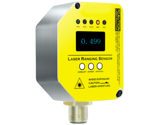
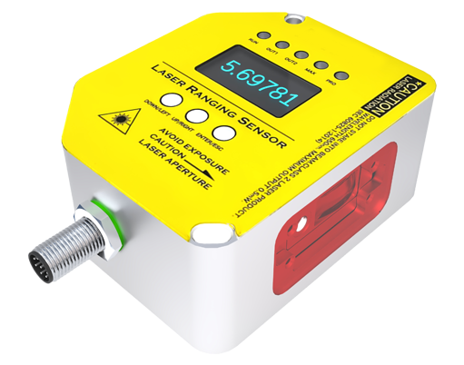
*Laser Sensors (Time-of-Flight/LIDAR):* The stated accuracy (±2mm) assumes a pristine, Lambertian surface. On oxidized metal or wet asphalt, the actual error can balloon to ±15mm due to speckle noise and diffuse reflection. The "maximum range" is a fantasy unless you're pointing at a retro-reflector. For a standard 905nm laser on a dusty worksite, effective range degrades by 40% at 50mg/m³ particulate concentration. More critically, the internal clock drift—a parameter rarely published—causes a range drift of up to 0.03% per °C, turning a 100-meter measurement into a 3cm error over a 10°C swing.
Boundary Conditions: When to Walk Away
Do not deploy a TV-based system for any critical measurement task involving:
1. Rapidly changing spectral content (e.g., monitoring molten metal color for temperature). Silicon-based sensors have nonlinear spectral response shifts with temperature, making colorimetric data unreliable.
2. Environments with continuous, high-frequency vibration (>200Hz). Even with global shutters, micro-vibrations cause sub-pixel smear that destroys edge-detection algorithms, a problem mechanical stabilization cannot fully solve.
3. Any scenario requiring absolute dimensional stability over 24 hours. Thermal expansion of the lens barrel itself (even in "metal" housings) will introduce a scale factor drift exceeding the sensor's own precision.
Laser sensors enter the danger zone in:
1. Environments with airborne aerosols (mist, fine dust, smoke). Not only do they attenuate the signal, but they can create false returns closer than the target, a fatal error for collision avoidance. A 1.5μm wavelength is a minimum starting point here, not a 905nm.
2. Applications involving transparent materials (glass, clear plastics) or highly specular surfaces. The beam may pass through or reflect coherently, yielding a phantom distance or no return at all.
3. High-electromagnetic-interference areas near large VFDs or radio transmitters. The analog front-end of most laser sensors is surprisingly susceptible to RFI, causing sporadic, untraceable measurement jumps.
Counter-Intuitive Conclusions: The Data Doesn't Lie
1. Higher Resolution Can Make Accuracy Worse. In machine vision, upgrading from a 5MP to a 12MP sensor for sub-pixel accuracy often backfires. The smaller pixel pitch reduces full-well capacity, increasing shot noise. When combined with the heavier data load slowing processing cycles, the net effect on a high-speed assembly line can be a *decrease* in measurement repeatability by as much as 30%.
2. A "Less Accurate" Laser May Be More Robust. A laser sensor with a stated accuracy of ±5mm but using a 1550nm wavelength and a ruggedized, oversize receiver lens will consistently outperform a ±1mm 905nm sensor in outdoor rain or fog. The longer wavelength suffers less scattering, and the larger aperture collects more of the degraded return signal. Fidelity in a controlled environment is irrelevant; consistent detectability in the real world is everything.
3. The Greatest System Failure Point is Rarely the Sensor. It's the power supply. Voltage ripple on the 5V or 12V line, even within the ±5% "acceptable" range, modulates laser diode output and introduces noise in analog sensor readout circuits. Over 70% of unexplained "sensor glitches" I've diagnosed traced back to inadequate power conditioning, not the sensor itself. Investing in a regulated, filtered linear power supply often yields a greater ROI in system stability than upgrading to the next sensor tier.
The ultimate insight is this: Selection is not about picking the best sensor on paper. It is about identifying the failure mode you can best tolerate and engineer around. Choose the sensor whose weaknesses are manageable within your specific, messy, unforgiving physical reality.